CE 432 2021 Fall ESP32-Video Streaming Web Server and Robot Car
Sophie Turner
sjturner@fortlewis.edu
ESP32-CAM Introduction
1. Introduction This tutorial continued to discover the different capabilities
that the ESP32-CAM has. ESP32CAM
was used to live stream a video and connect to a BMP180 sensor and
display the altitude, pressure, and temperature on the web server. A remote-controlled car robot was also created where the ESP32-CAM was
attached.
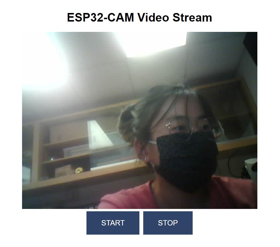
Task 1. ESP32-CAM
was used to video stream on a web server with start and stop buttons.
Figure 1. Screen shot of ESP32-CAM video stream web server.
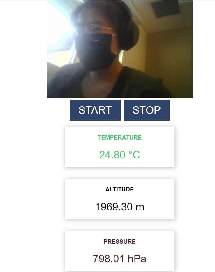
Task 2. The
objective of this task was to connect a BMP180 sensor to read
temperature, altitude, and pressure. Adafruit_PMP085 library was
installed for this task. The code was modified to display altitude
instead of humidity. The sensor read temperature (deg C), altitude (m), and pressure (hPa) and were displayed on the web server with the live video.
Figure 2. Screen shot of the ESP32-CAM video stream web server including my location's temperature, altitude, and pressure.
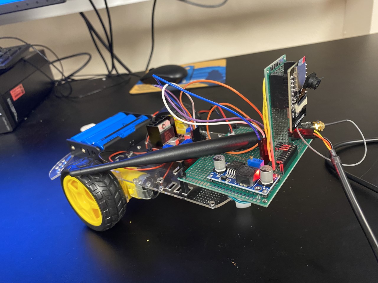
Task 3. A remote-controlled car was assembled and the ESP32-CAM was attached. A
mount for the ESP32 was created by soldering wires and header pins to a
PCB board to connect the ESP32 to the car. 3.7V battery cartridge,
L298N Motor Driver, voltage regulator and the soldered boards were attached to the car
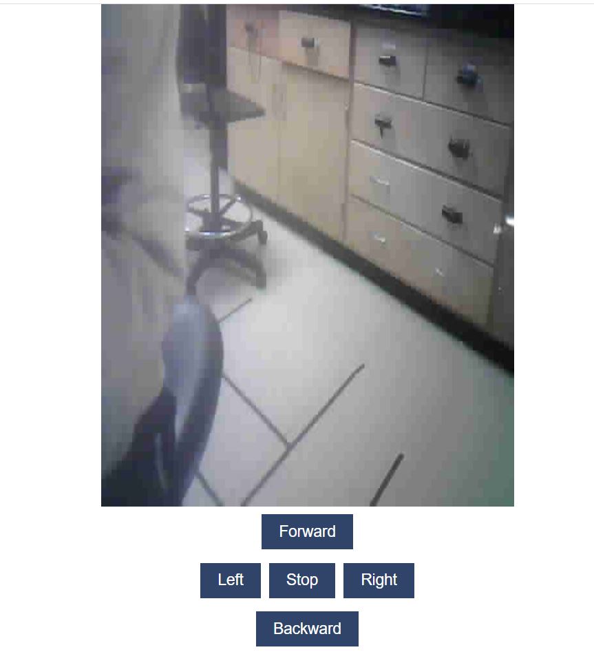
kit. The car is controlled by the webserver. A video streams on the web
server as well as a forward, left, stop, right, and backwards button to
control the robot car as seen in the video below.
Figure 3. Robot Car.
Figure 4. Video of the robot car moving.
Figure 5. Rotating the video image by 90 degrees.
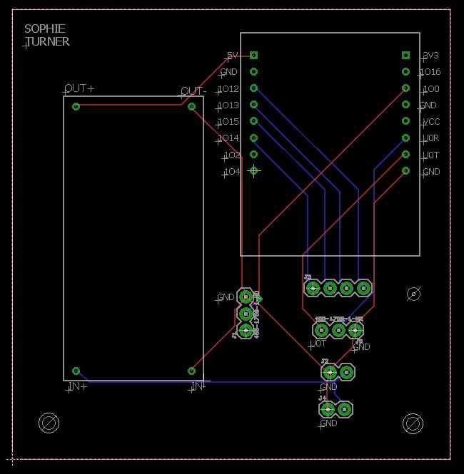
Task 4. Task 4 was to design a PCB in Eagle replacing
the prototype board. In Eagle I designed a PCB to hold the ESP32 and the
voltage regulator. Parts were soldered on the board and the car was retested.
Figure 6. PCB design in Eagle board view.
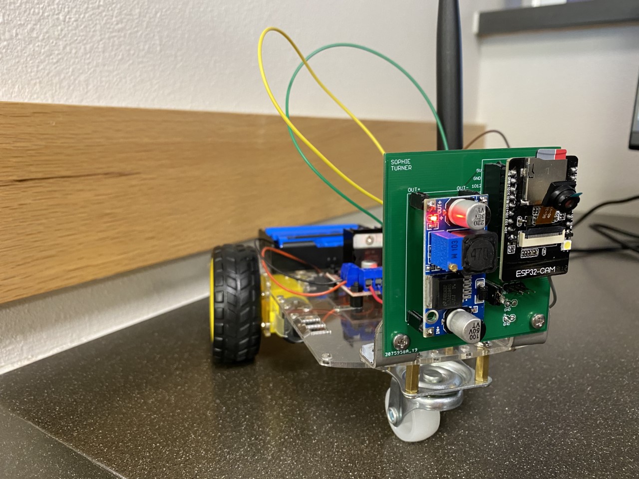
Figure 7. Robot Car with my PCB mounted.
Figure 8. Robot car functionality demonstration with my PCB design.
2. Discussion I
was able to successfully complete all the tasks. This tutorial allowed
me to see and use the different capability the ESP32-CAM has. I also
assembled the car successfully. I gained more practice with soldering.
I
enjoyed assembling the car and soldering the connections. The PCB was
designed and fabricated. The car functions properly and the PCB design
was a success.