CE 432 2021 Fall ESP32-CAM Introduction
Sophie Turner
sjturner@fortlewis.edu
ESP32-CAM Introduction
1. Introduction ESP32CAM
was used to stream a live video and perform face
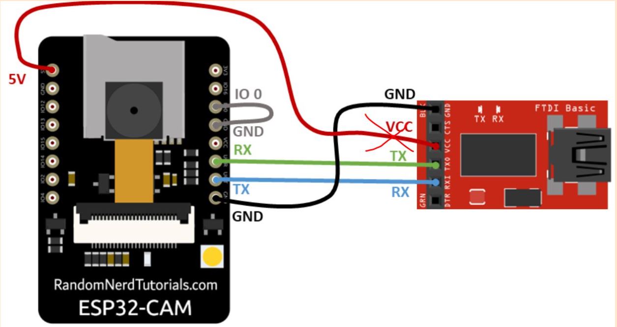
recognition and face detection. The ESP32CAM was connected using a FTDI
cable. By connecting to WIFI and accessing the IP address of the
ESP webserver, the CameraWebServer was used to stream a live video. The
flash light on the ESP32CAM was also modified in this lab by using
Arduino.
Figure 2. ESP32-CAM to power connection.
3. Results
Task 1. ESP32-Cam
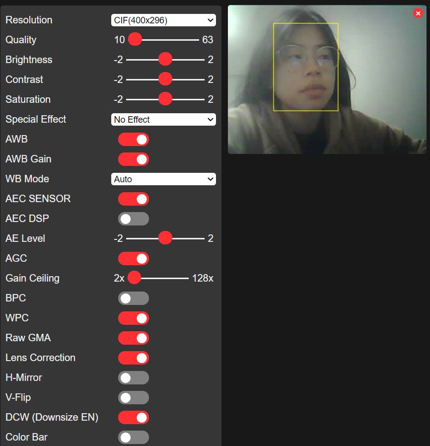
was connected to CameraWebServer using WIFI. Live video was streamed
from the camera using the IP address of the ESP webserver. Face
detection was accomplished in the CameraWebServer as seen in Figure 3.
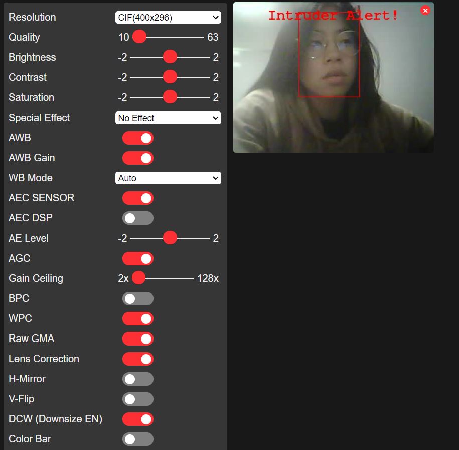
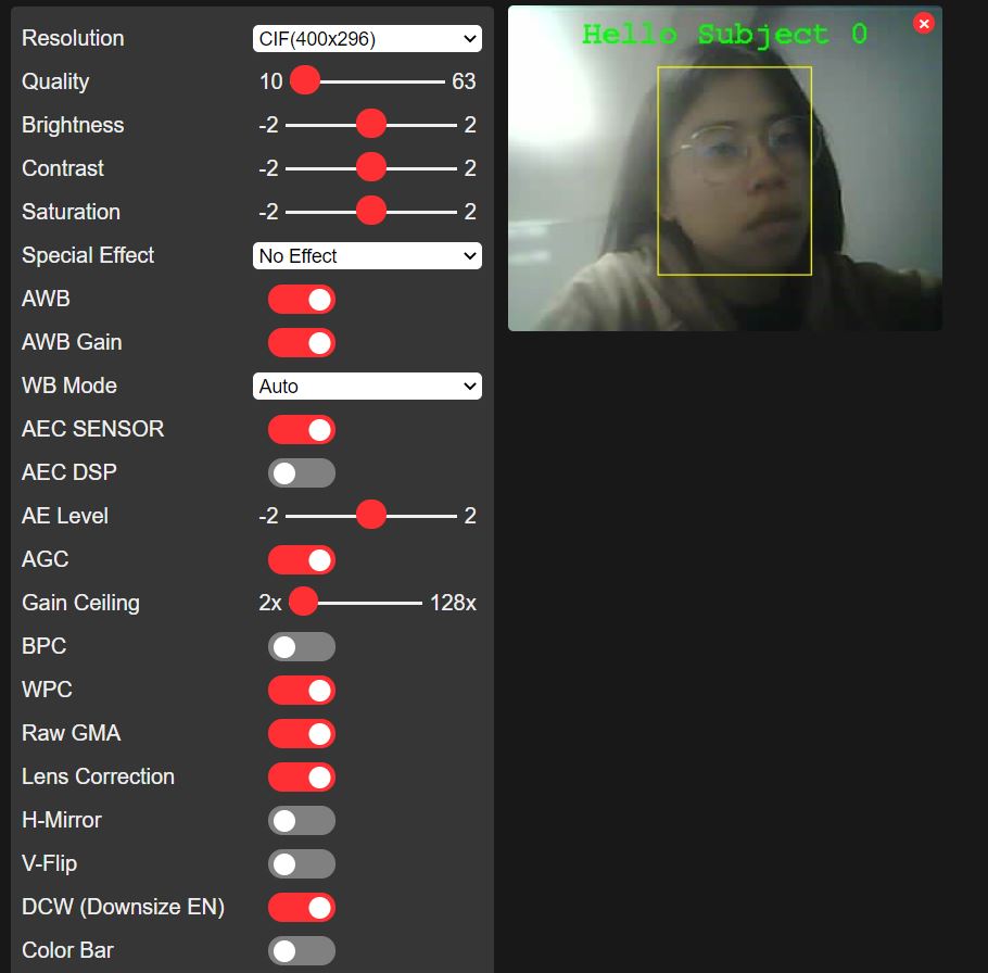
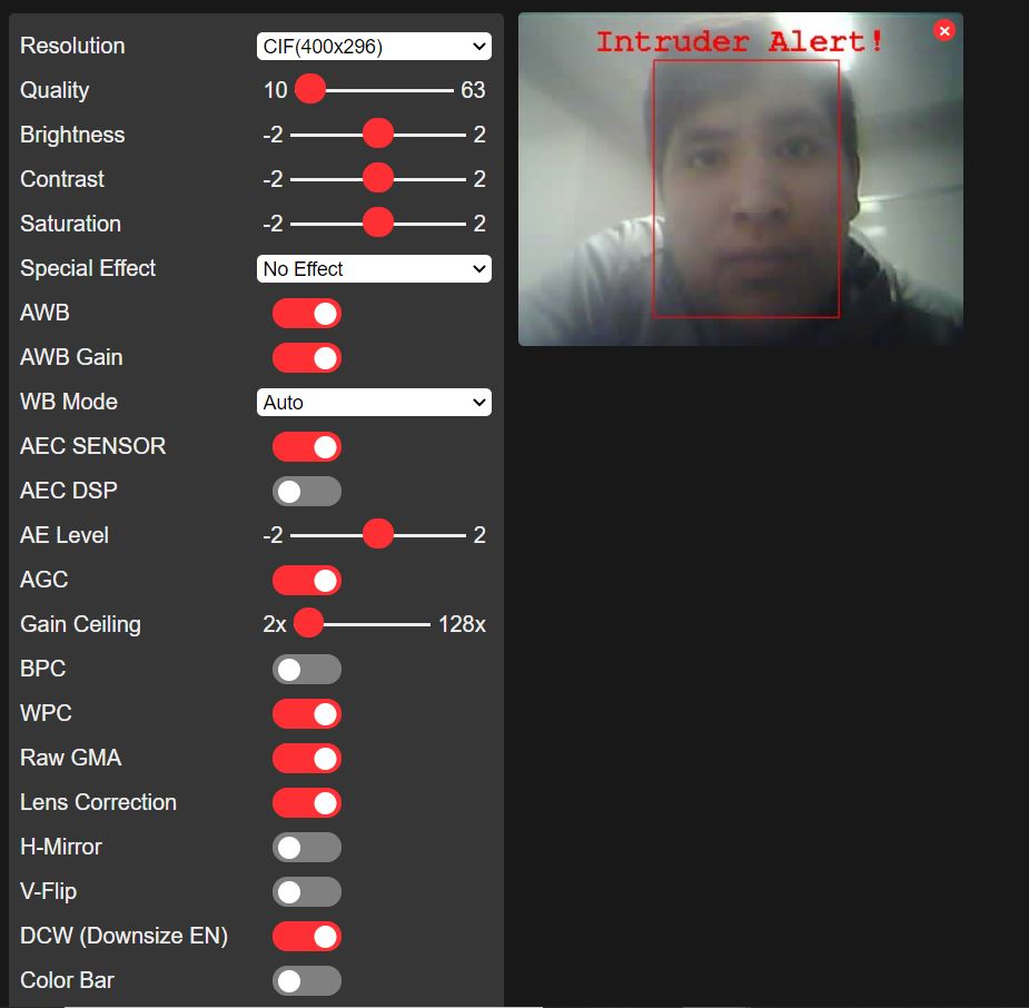
Face recognition was also tested and before my face was enrolled in the
system; I was seen as an intruder as seen in Figure 4. After I enrolled
my face, I was recognized as seen in Figure 5.
Figure 3. Face detection using CameraWebServer.
Figure 4. Face recognition before enrolling facial features.
Figure 5. Face recognition after enrolling facial features. Figure 6. Another person testing face recognition after I enrolled my face.
Task 2. The GPIO4 pin is connected to the flash light on the ESP32
module. Using Arduino IDE I was able to control the flash light. The
videos below demonstrate the flash blinking. Figure 8 demonstrates the
flash turning on and off using a push button and the last video shows
the flash brightness changing by modifying the PWM.
Figure 7. Flash light blinking every 2 seconds.
Figure 8. Flash light controlled by a push button.
Figure 9. Flash light brightness changing with PWM.
2. Discussion I was able to successively complete all the tasks. The resistor on the ESP32-CAM was successively rotated and resoldered
back on the board. This project allowed me to refresh using Arduino
IDE. I was able to learn about the basic functionalities that the
ESP32-CAM has through this tutorial.