CE 432 2021 Fall
Balancing Car
Sophie Turner 
sjturner@fortlewis.edu

Balancing Car

1. Introduction
This purpose of this project is to build a two wheel car and program it to balance using an Arduino. A frame for the car was built using metal poles and rectangular plastic boards. 3D parts were created for the motors and brackets to hold the board. Multiple tasks were done before balancing the car to help understand the code and components. The car was first prototype using a bread board. A PCB was designed and fabricated based on the prototype. A PID feedback loop was used to allow the car to balance. All components to this project can be found here.

2. Methods
This balancing robot required many components that are listed below. I followed this tutorial for all the steps to complete the tasks and this guide for the balancing car.

Quantity Component
1 Accelerometer
2
NEMA17 Stepper Motor
2 A4988 Stepper Motor Drivers
1 Arduino Uno
1 Breadboard
1 100uF capacitor
2
Wheels
2
3D printed Wheel adapters
2
3D printed board brackets
2
3D printed Motor holder brackets
Many
Jumper Wires
4
Metal Rods
2
Boards for body of car
16 Nuts
1 Open-Smart 2.4 GHz transceivers

3. Results

Task 5.
For Task 5 I modified the MPU code to display raw acceleration data for the X axis. The MPU was inserted in a breadboard at a 90-degree angle as shown in Figure 2. The output values are the raw acceleration data for X axis and are all 8500+ due to error. The demonstration video (Figure 1) is to verify the accelerometer was working. Also, in Figure 1 and 3 you can see the difference between the gyro reading and the acceleration reading.

Figure 1. Demonstration video of the accelerometer readings on the Serial plotter.


Figure 2. Serial monitor outputting the raw acceleration data for X axis.

Task 6.
The gyro readings needed to be averaged for a steadier reading. The code averages the first 500 gyro readings for calibration. Figure 4 shows the gyro_pitch_calibration printed in the serial monitor to be around -70.

Figure 3. Demonstration video of the gyro readings on the Serial plotter.


Figure 4. Serial monitor outputting gyro_pitch_calibration with a delay of 500.

Task 7.
Task 7 was to blink an LED at 1Hz. The purpose of the blinking LED was to create a time delay using a feedback loop from the PID controller. 1,000,000 us were added to the loop timer for the LED to blink at 1Hz.

Figure 5. LED blinking at 1 Hz.

Task 8.
Task 8 was to create the car and mount the MPU650 sensor to the breadboard. The serial monitor should output 0 degrees and ±90 degrees when leaned to the left and right. The video below demonstrates the sensor outputting around 0 degrees and then when leaned to the right +90 and when leaned to the left about -90.

Figure 6. Serial monitor outputting the accelerometer angle when the balancing car is tilted to the left and right.


Balancing Car
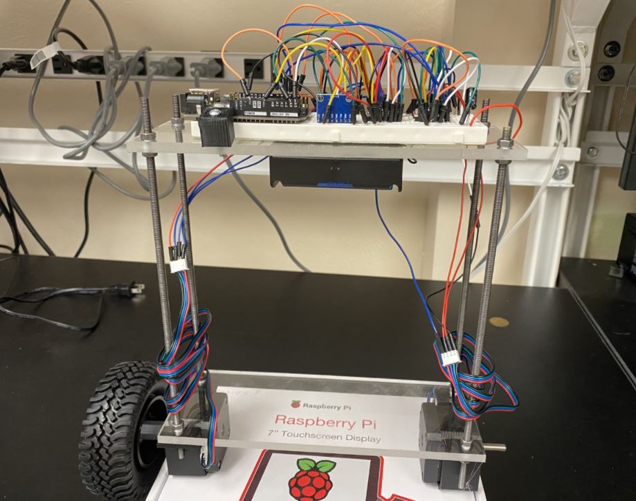
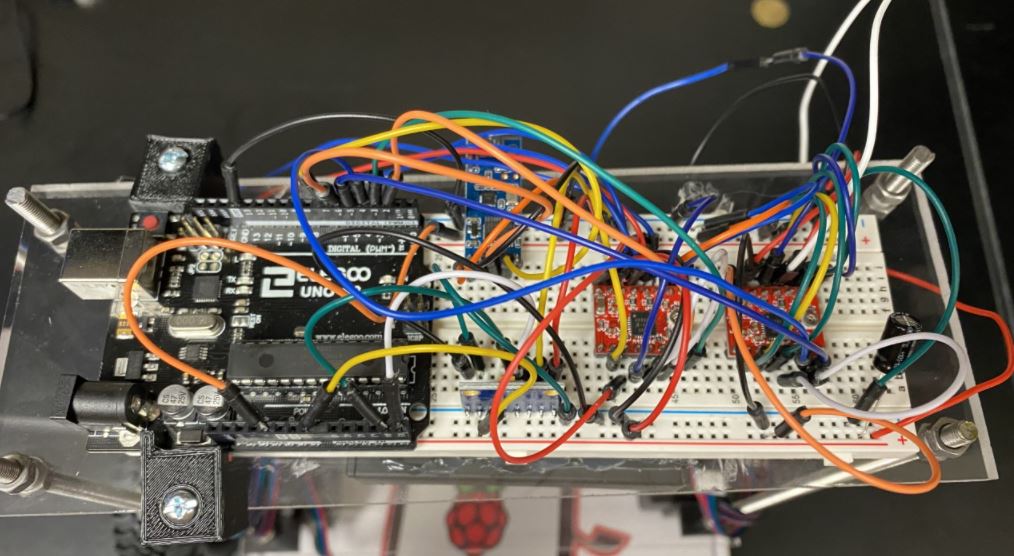
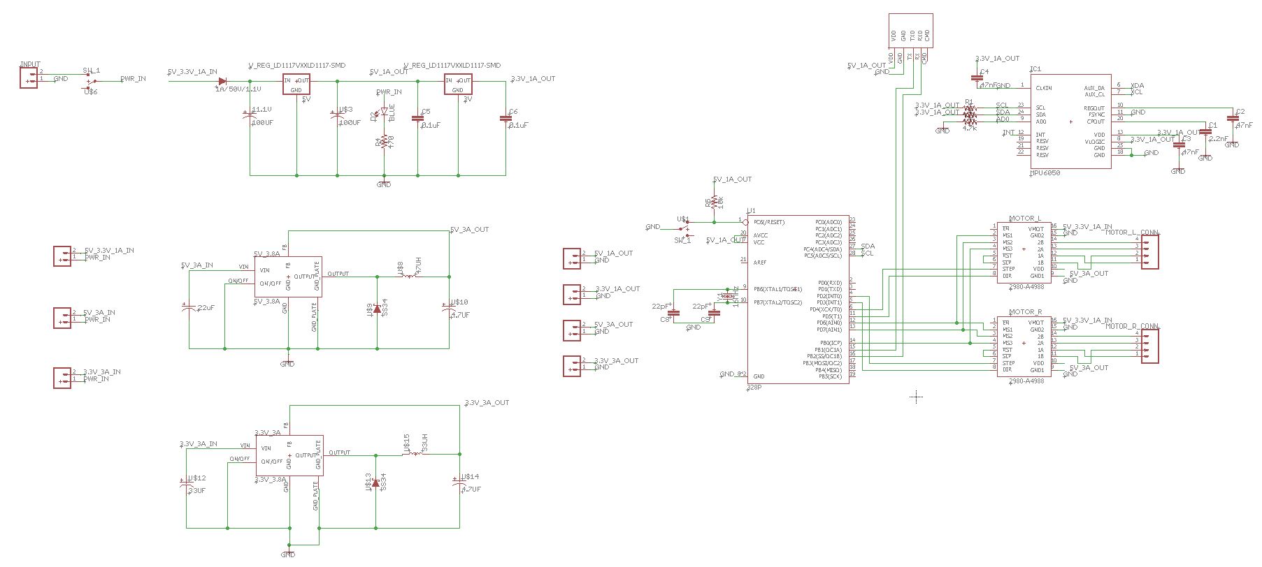
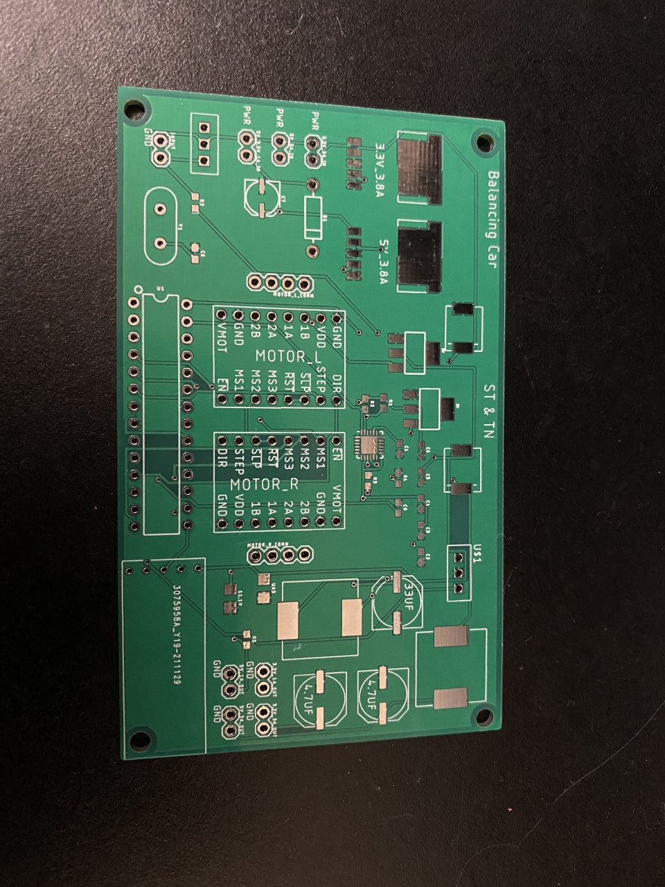
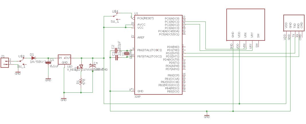
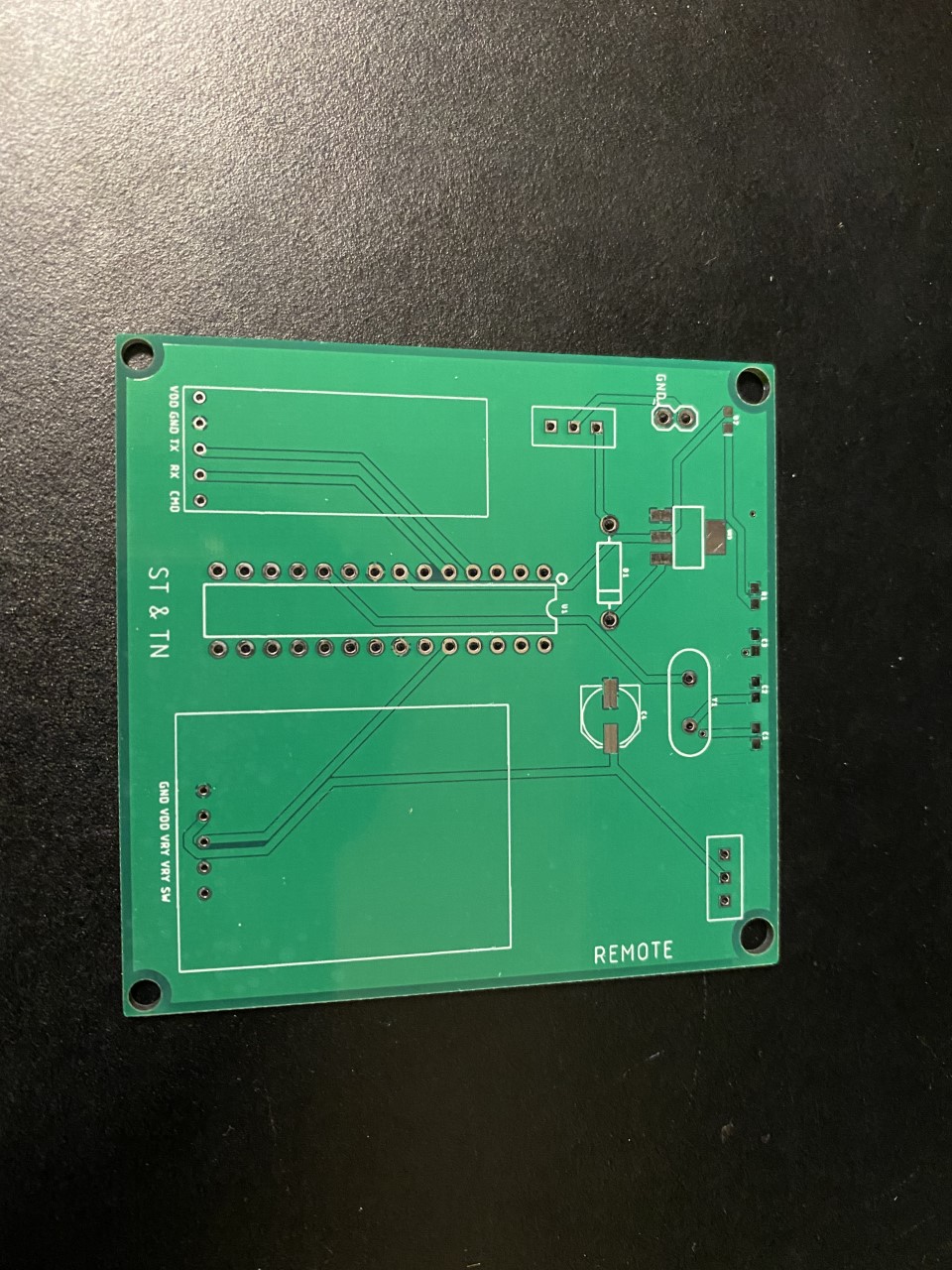
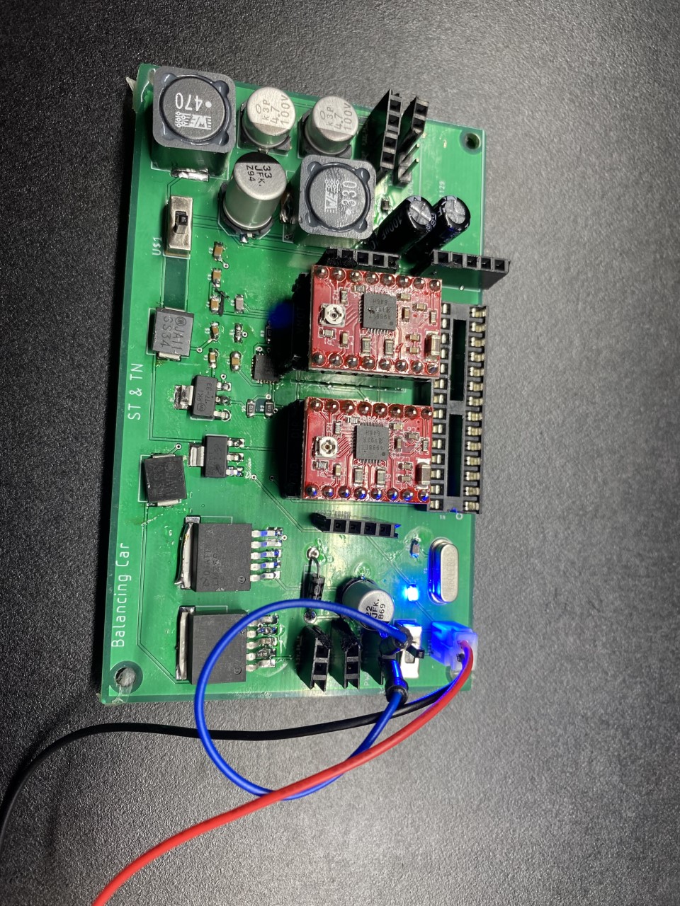
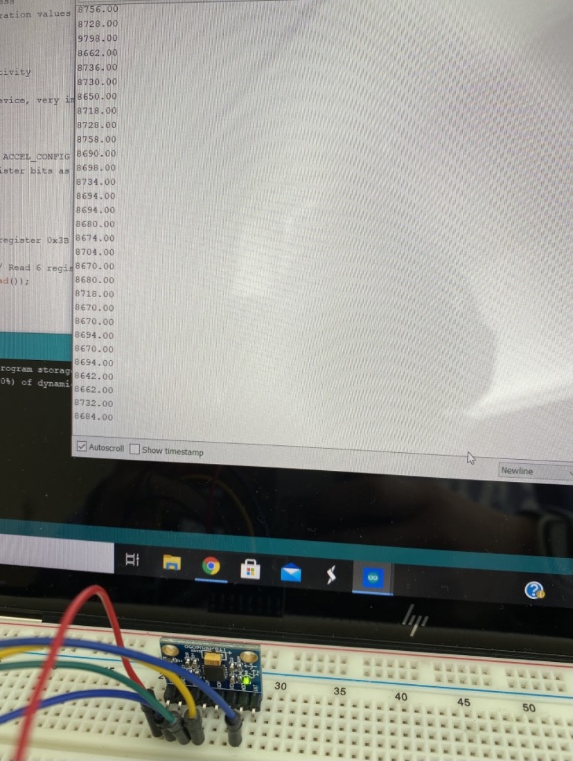
The car was assembled, wired, and tested to make sure the components on the car worked. A PCB was created in Eagle to reduce the amount of wires seen. A PCB for a remote to control the car was also created. The components were soldered onto the car PCB.


Figure 7. Balancing robot frame and prototype board.


Figure 8. Wiring and components for the balancing car.


Figure 9. Eagle schematic for the car.


Figure 10. PCB for the car.


Figure 11. Eagle schematic for the remote control.


Figure 12. PCB for the remote control.


Figure 13. Finished car PCB.

The car was tested by trial and error. Different accelerometer calibration values were tested as well as the gain values in the code. In the demonstration below is the car balancing.

'
Figure 14. Demonstration of the balancing car.

The joystick was not implemented with the car. The car PCB was also not programmed and tested with the motors.

2. Discussion
This project was very interesting and I gained a lot of knowledge and experience. Future work would be to implement the car PCB as well as use the joystick. This project was very interesting. Bringing in the knowledge that we learned throughout the semester to a real world problem allowed for a better understanding.