
1. Introduction
The purpose of this lab was to use the liquid-crystal display (LCD) to produce an image. A LCD1602 was used in this lab as well as potentiometer, thermistor, DHT11 temperature and humidity sensor, TMP36
low voltage temperature sensor, and an IR detector. The ATMega 328p MCU
was removed from the Arduino and placed on the bread board for two
tasks in the module. Task 9 wants a seven second display (SSD) to
display the output from the DHT11 humidity and temperature
sensor.
2. Methods
Arduino
Undo R3 was used to complete 9 tasks for this lab. A LCD1602 was used
to display "Hello World", "Durango", temperature, and humidity from
different sensors.Sensors such as DHT11 temperature and humidity
sensor, thermistor, TMP36 low voltage temperature sensor, and a IR
remote were used throughout this lab. For more detailed methods visit http://www.yilectronics.com/Tutorials/Arduino_Basics/Tutorial_4_lcds_sensors/lcds_sensors.html.
3. The Code and the Results
Display "Hello World!" on the first line starting with 'H' on the second rectangle. Also, the counter counts from 0-5.
Figure 1. Video displays "Hello World!" on a LCD and counts up from 0-5.
Figure 2. Code to print out "Hello World!" and have a counter from 0-5.
Durango
is displayed on the LCD. Durango moves along the LCD from left to right
and blinks three times when it hits the middle of the display.
Figure 3. Displays "Durango" on a LCD.
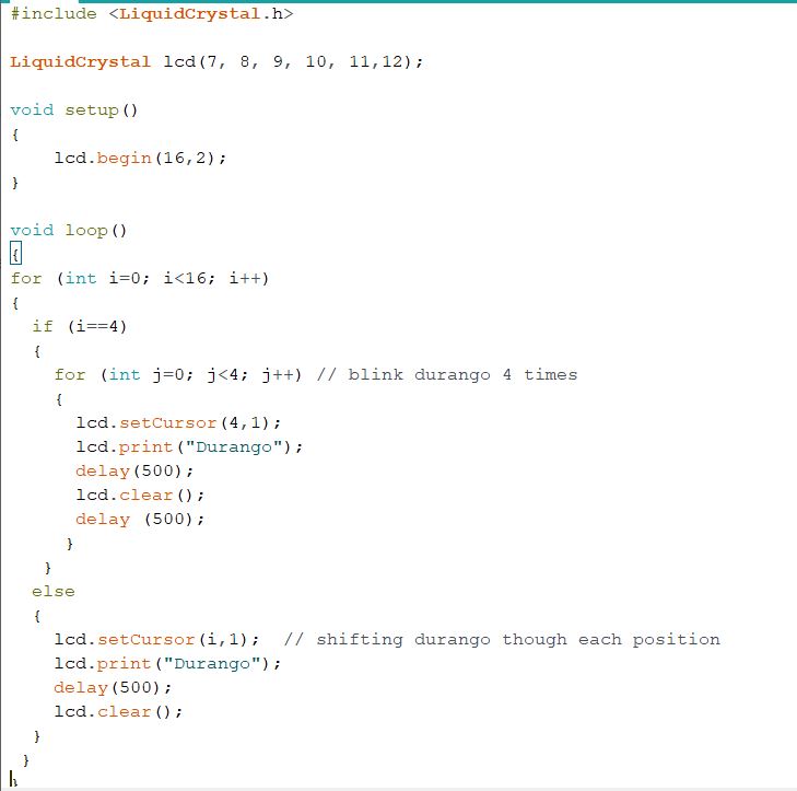
Figure 4. Code to move "Durango" across the screen.
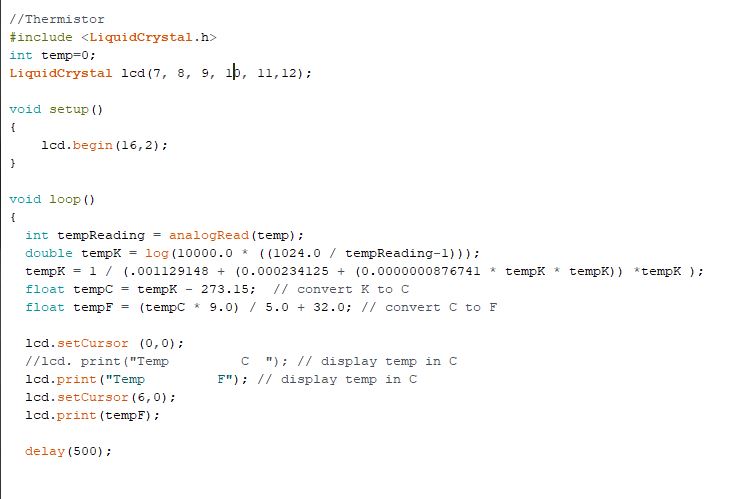
Temperature was displayed on the LCD using a thermistor. The thermistor was pinched to display my temperature.
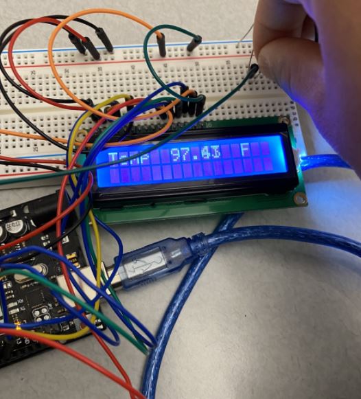
Figure 5. LCD displaying temperature from a thermistor.
A
DHT11 digital temperature and humidity sensor was used to display
humidity and temperature on an LCD. The video below shows that
the humidity changing as you blow on the sensor.
Figure 7. DHT11 sensor displaying humidity and temperature on the LCD.
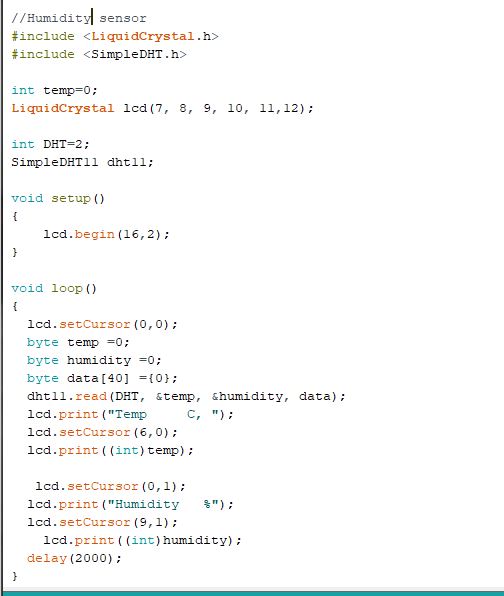
Figure 8. Code for display temperature and humidity on a LCD using a DHT11 sensor.
LCD displaying temperature using a TMP35.
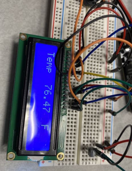
Figure 9. LCD displaying temperature using a TMP35.
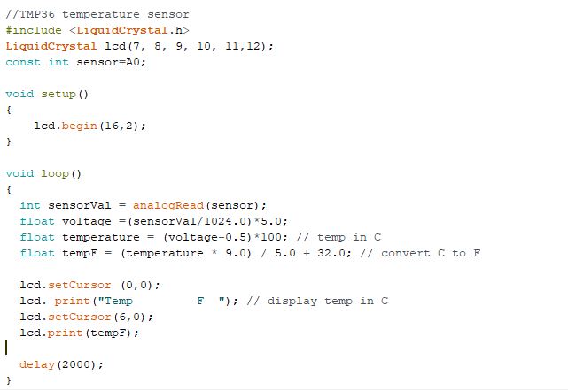
Figure 10. Code to display temperature on a LCD using a TMP35 sensor.
An
IR remote was used to control the output on a LCD. Decimal numbers were
converted into Hexadecimal in order to display the remotes input.
The video below demonstrates the remote output onto the LCD screen.
Figure 11. LCD displaying IR remote output.
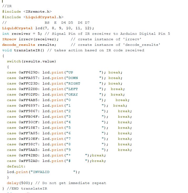
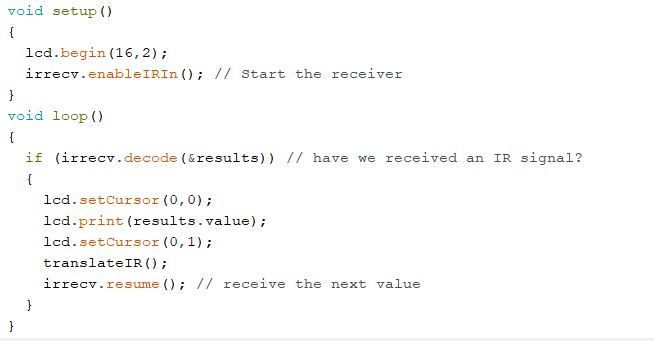
Figure 12. Code to display the IR remote output onto a LCD.
For
Task 8 the ATMega328p MCU was removed from the Arduino board and placed
on the bread board. A LED was wired to the 328p chip and coded to
blink.
Figure 13. Video of a LED blinking to test a barebone 328p MCU.
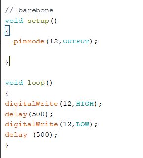
Figure 14. Code for a blinking LED using a barebone 328p MCU.
For
Task 9 the barebone ATMega 328p MCU was used to build a digital
temperature meter. The DHT11 sensor was used as well as the
four-digit SSD to display the temperature and humidity detected.An interrupt
service routine was used in the code to update the temperature and
humidity display. The SSD switches between temperature (F) and humidity
(P).
Figure 15. Demonstrating a SSD switching from displaying humidity and temperature.
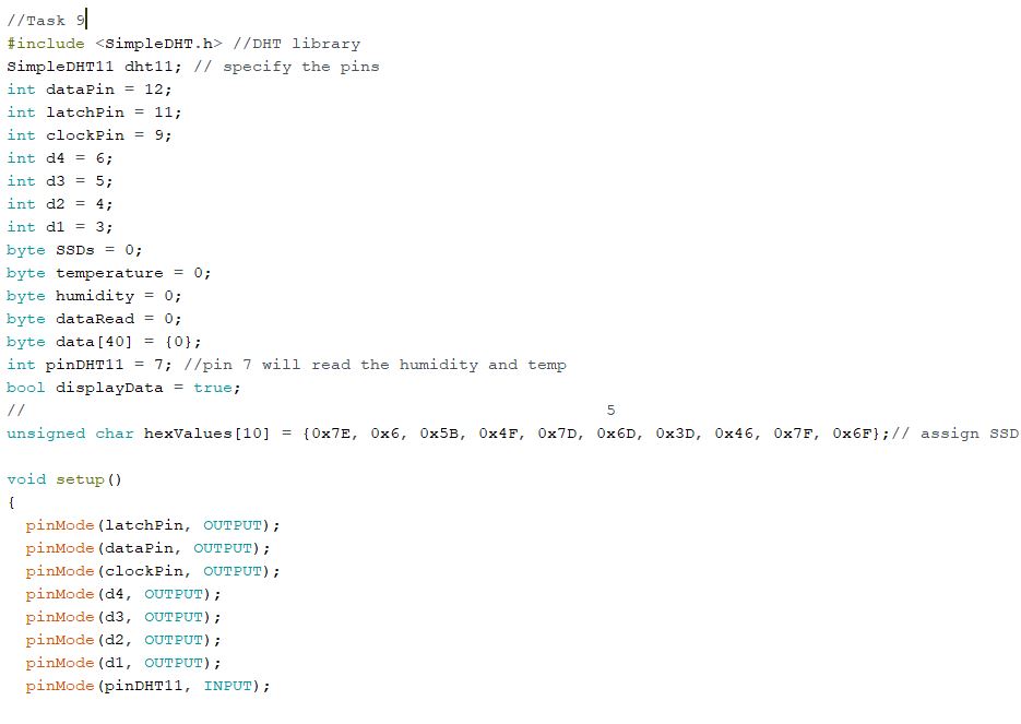
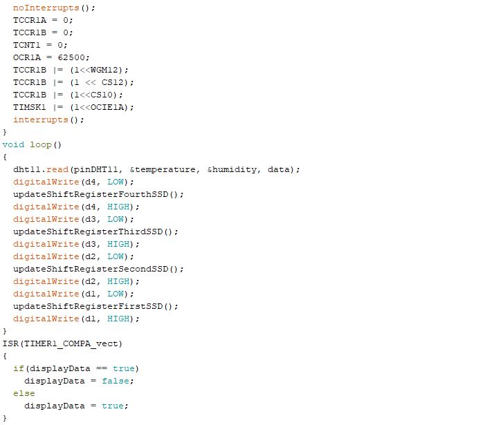
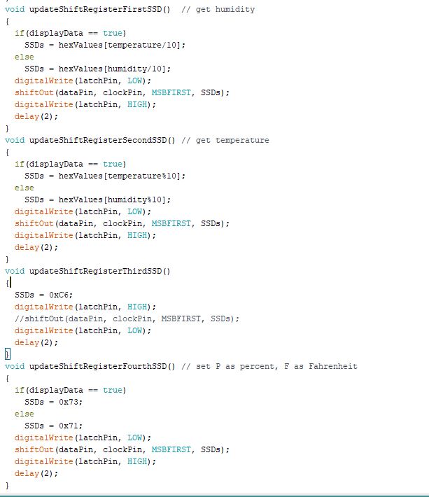
Figure 16. Code to display temperature and humidity on a SSD.
4. Discussion
The
main portion of this lab was to wire and code different parts to
display on a LCD. After long hours of wiring the board, Tasks 1-8 are
completed, and the results are as wanted. For Task 9 my SSD
switches between humidity (P) and temperature (F) detected by the
sensor. My code is displaying P and F twice on the third and
fourth SSD and will need to be adjusted for the future. My SSD
also only displays a two-digit input which will also need to be
modified.