CE351
2020 Fall
Lab 3: LED and SSD
Sophie Turner
sjturner@fortlewis.edu
LED and SSDs
1.
Introduction
In Lab 3 light-emitting diodes (LED) were
programmed using Arduino UNO R3 controller board. The LEDs were
programmed to blink, and to turn on and off using a push button. A seven second
display (SSD) was also programmed with Arduino. The SSD displayed numbers
from 0-9 when manually wired, using a digital decoder, and a shift register. The decoder and shift register reduces the amount of digital pins needed to control the seven pins on the SSD.
2.
The Code and the Results
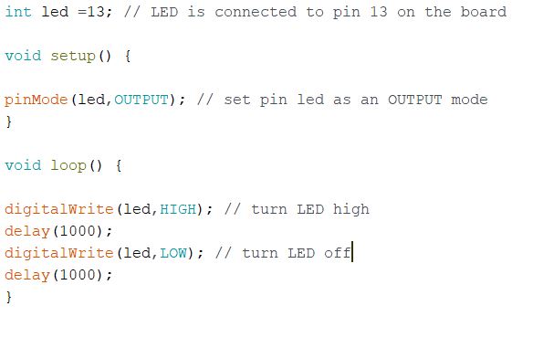
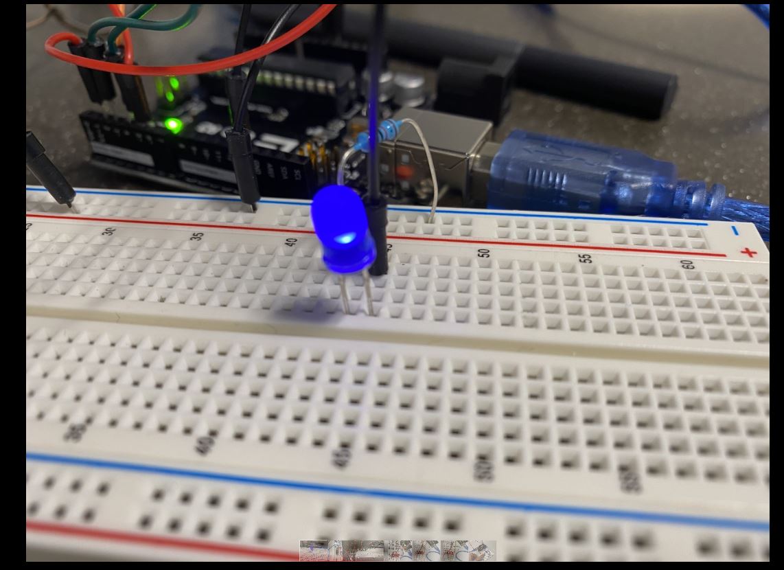
The following is code to light up a LED. Figure 2 shows a blinking LED. The delay time will control how fast the LED will blink.
Figure 1. code that blinks one LED per second.
Figure 2. LED blinking once per second.
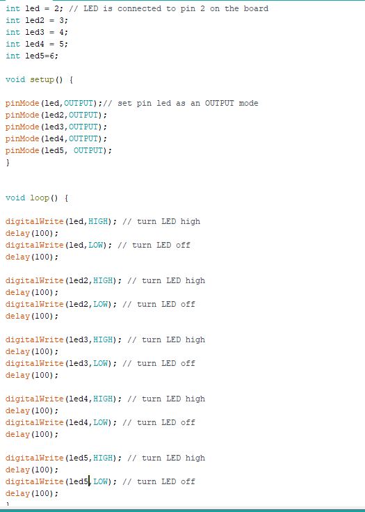
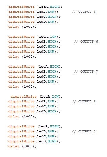
LEDs can also be coded to blink in different patterns. In the video below five lights will blink in a sequence.
Figure 3. Code for 5 LEDs blinking in a sequence.
Figure 4. Example of LEDs blinking in sequence.
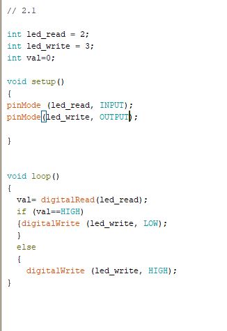
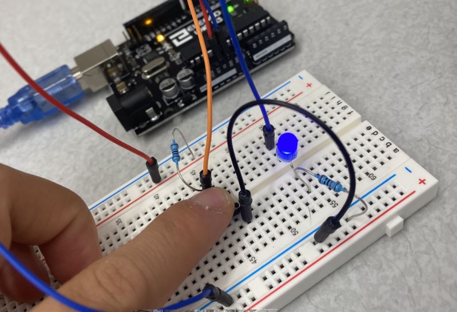
LEDs can be coded to turn on and off with a push button. Figure 5
is the code to turn on a LED with a push button. To have the push
button turn off the LED, digitalWrite would be LOW in the else statement
and HIGH under the if statement.
Figure 5. Code for a push button to turn on a LED.
Figure 6. Push button is coded to turn on a LED.
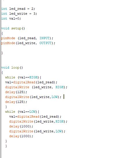
The following code blinks the LED four times a second; after the button is pushed the LED blinks one time per second. Figure 7. Code to blink LED four times per second then to one time per second after a push button is pushed.
Figure 8.Example of LED blinking four times per second then to one time per second after a push button is pushed.
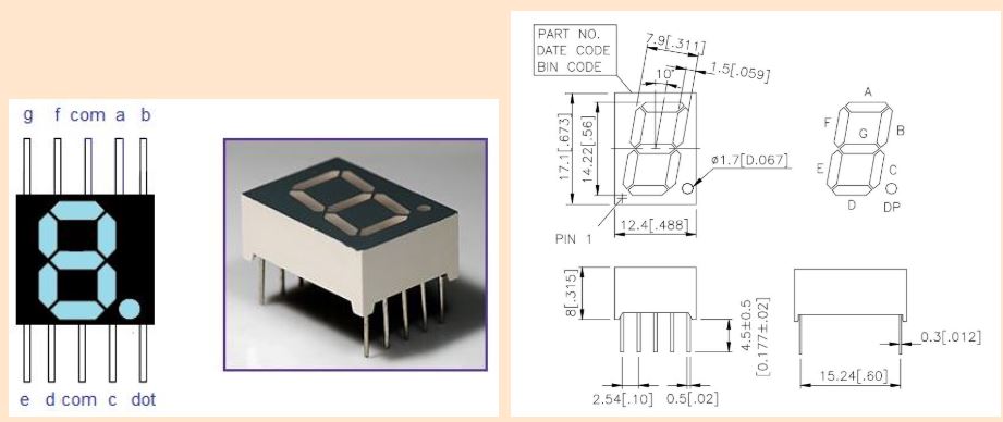
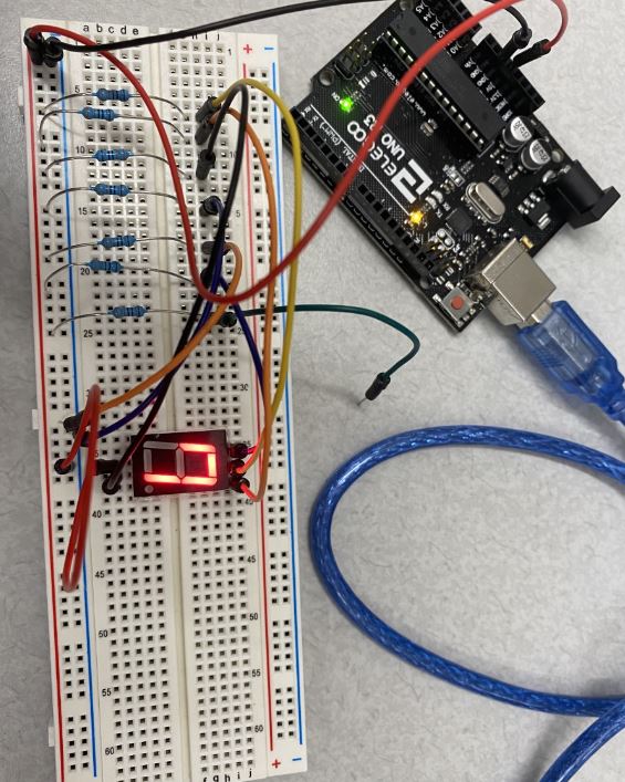
Seven Segment Display (SSD) A SSD can display numbers and letters using different LED
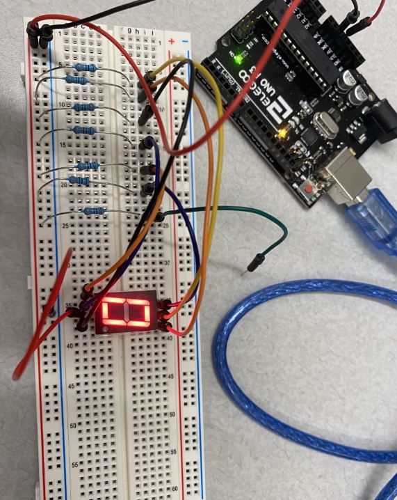
combinations. In Figure 10 the SSD is manually wired to display numbers
from 0-9 using the pin map below. Figure 9. Pin map for the SSD.
Figure 10. SSD displaying 0, 7, and 8.
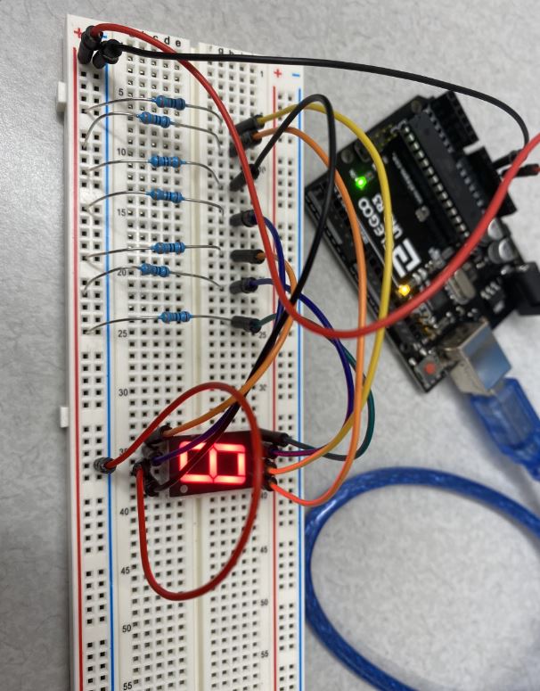
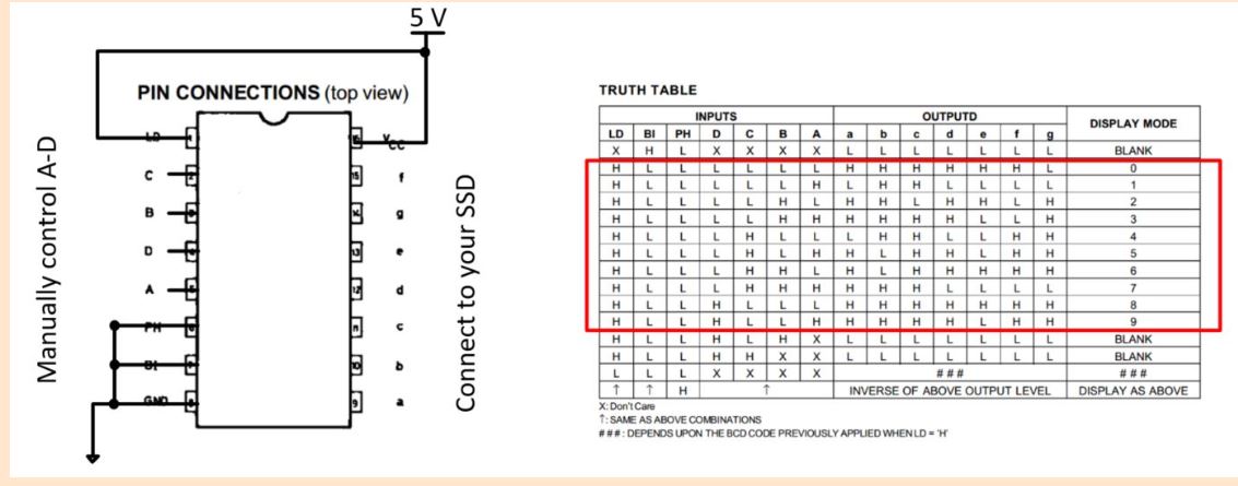
A more pin efficient way to display numbers from 0-9 is to use a Digital Decoder. A M74HC4543 Digital Decoder was used to control the
SSD. The schematic in Figure 11 was used to wire the decoder to
the SSD. The truth table was used to display the numbers by turning
on different pin combinations. Figure 12 contains the code that
displays numbers 0-9. Figure 11. Decoder schematic and truth table.
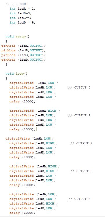
Figure 12. Code to display numbers 0-9 with the decoder.
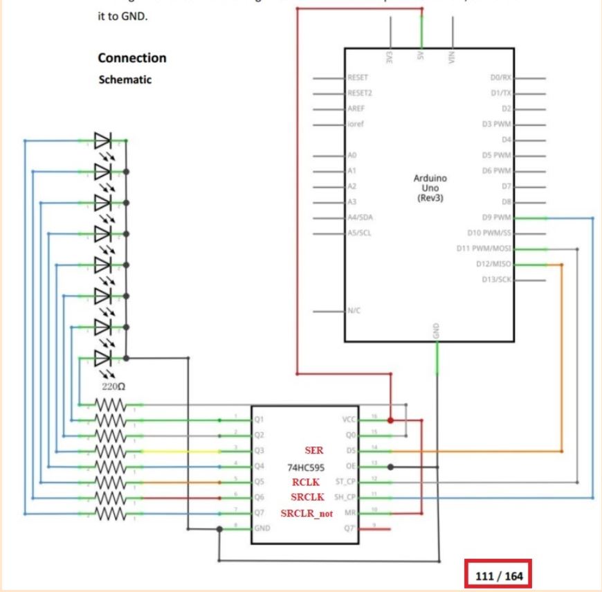
A shift register was also used to control the SSD. A 74HC595N shift
register was used for the lab. Figure 13 was the schematic used to wire
eight LEDs to a shift register as well as the SSD-shown later. Figure 13. Shift register connection diagram to 8 LEDs.
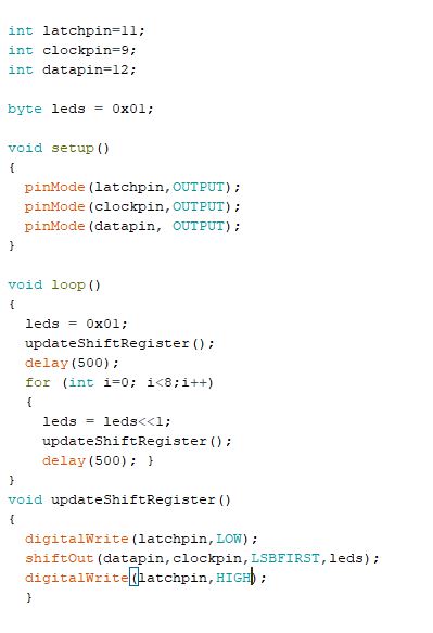
Figure 14. Blinking 8 LEDs using a shift register.
Figure 15.Code to blink 8 LEDs using a shift register.
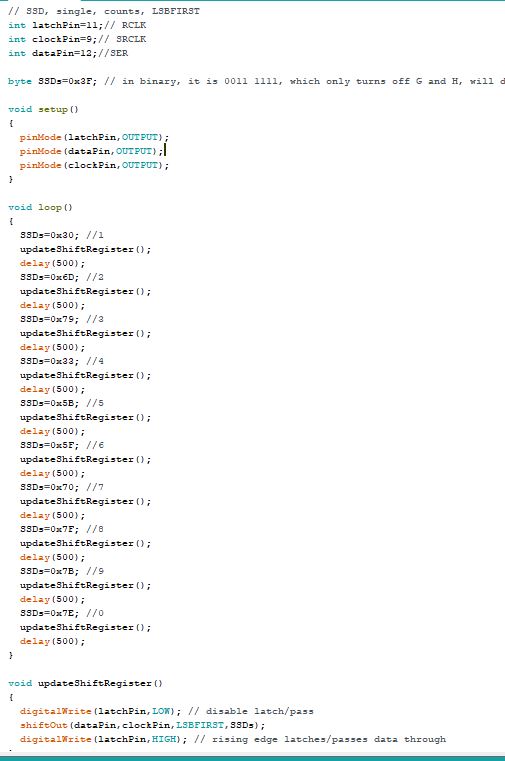
Figure 16. Example of displaying numbers 0-9 using the shift register.
Figure 17. Code to display 0-9 using the shift register.
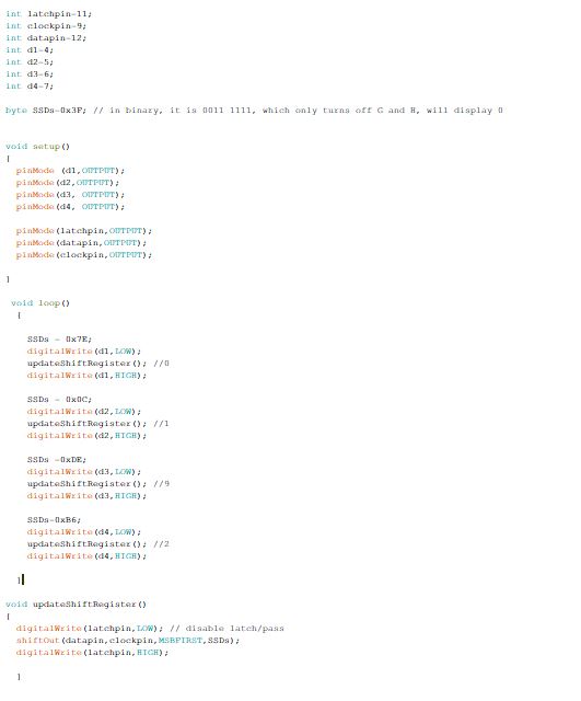
SSDs can also be combined to display more digits. A 4-digit SSD was used to display 2019. Figure 18. SSD displaying 2019.
Figure 19. Code to display 2019 using a shift register.