ENGR338
2021 Spring
Lab 1: Review of Circuits and LTSpice
Sophie Turner
sjturner@fortlewis.edu
Review of Superposition, Thevenin's Equivalent
Circuit, and LTSpice
1. Introduction
The purpose of this lab was to review Superposition, Thevenin equivalent
circuits, time delay, and LTSpice. Two circuits were given. For Task 1
Superposition was used to solve for all currents and voltages throughout the
given circuit. LTSpice was used to verify the currents and voltages. Task 2
used Thevenin's Equivalent Theorem to solve for R-Thevenin (RTH), and the source
ETH. The time delay was also calculated and verified by LTSpice.
Task 1:
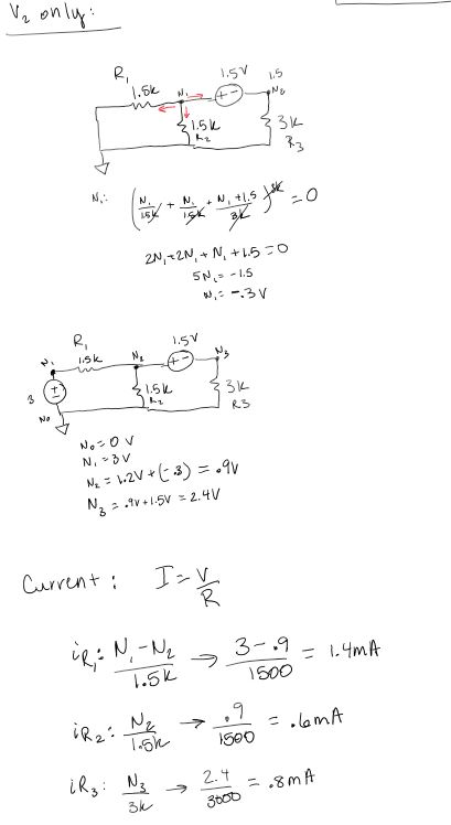
The following figure shows the hand calculations for the given circuit. The
voltages and currents were calculated using Superposition.
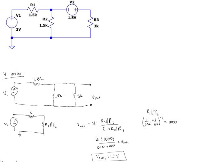
Figure
1. Hand calculations solving
the circuit using Superposition.
The following simulation shows that the current across R1 was 1.4mA, current across
R2 was 0.6mA, and the current across R3 was 0.8mA. Voltage was also calculated.
Voltage at node1 was 3V, node2 had 0.9V, and 2.4V was calculated at node3.
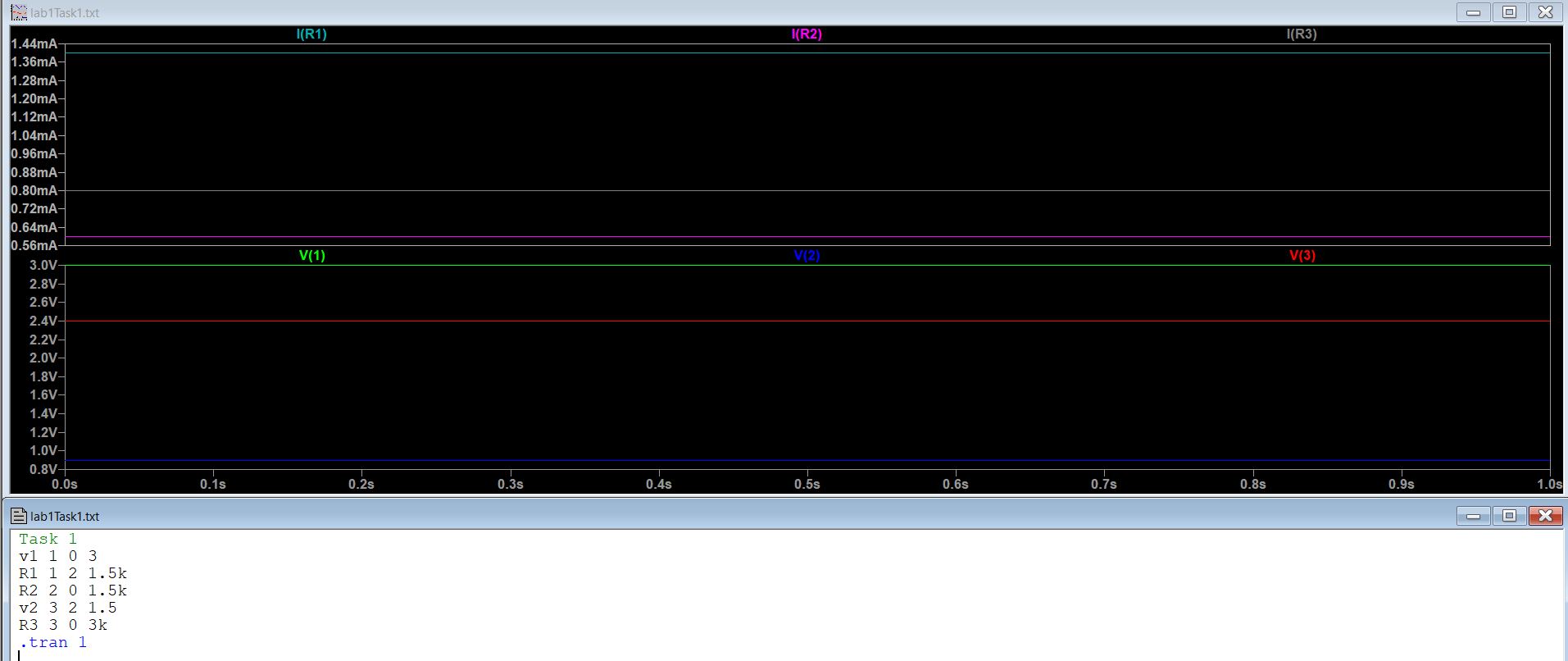
Figure
2. LTSpice simulation and code
that verifies the current and voltage from the hand calculations.
Task 2:
Thevenin's Equivalent Theorem was used to find the time delay for the
given circuit. RTH, ETH, and the time delay was all calculated as shown in the
figures below.
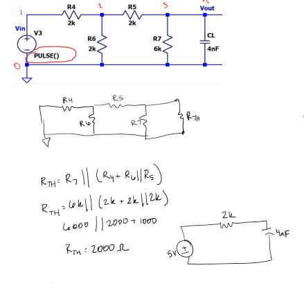
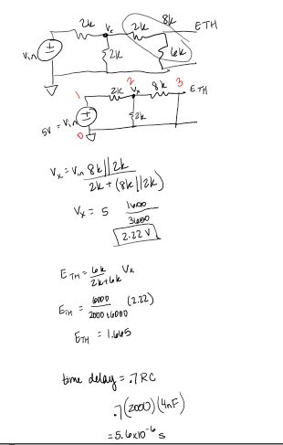
Figure
3. Hand calculations solving
for the Thevenin's equivalent circuit.
LTSpice was used to verify the hand calculations. The time delay was calculated
to be 5.6 µs and LTSpice calculated 0.5V1 (.7 time constant) to be 5.579µs. In the figure
below the blue curve shows the capacitor trying to charge to 5V.
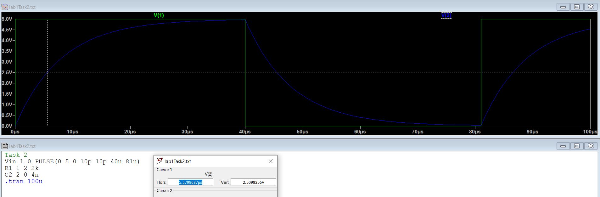
Figure
4. LTSpice simulation and code
that verifies the hand calculations.
2. Discussion
My hand calculations and the LTSpice simulations corresponded. This lab allowed
me to review Thevenin's Equivalent Theorem and Superposition Theorem.