Scott Orban
Zane Sauer
CE 432
Self Balancing CarProject
Introduction
The goal of this project was to design and prototype self balancing,
remote controlled robot product.
Methods
The robot used an MPU6050 accellerometer/gyroscope to read the angle it
was tilting to. The accelerometer data was read into an arduino uno
where PID calculations were performed and used for balancing. A
bluetooth module connected to the Arduino received commands from the
second bluetooth module/Arduino combo connected to an analog joystick.
Two NEMA 17 stepper motors connected to two A4988 motor drivers moved
the robot via an interupt service routine. The system was powered by a
12V battery pack. Each component was developed and tested individually before assembling the
whole robot together. Results
Video 1: A4988 stepper driver demo.
Video 2: Using a
potentiometer to control the speed of the stepper motor.
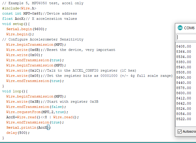
Figure 1: The raw accelerometer data.
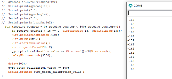
Figure 2: Averaged gyro_pitch_calibration_value.
Video 4: Blinking an LED at 1Hz using an ISR.
Video 5: Angle calculation with the MPU6050.
Video 6: Testing the
robot with the motors in full step mode.
Video 7: Testing the
robot in 1/8th step mode with wireless communication.
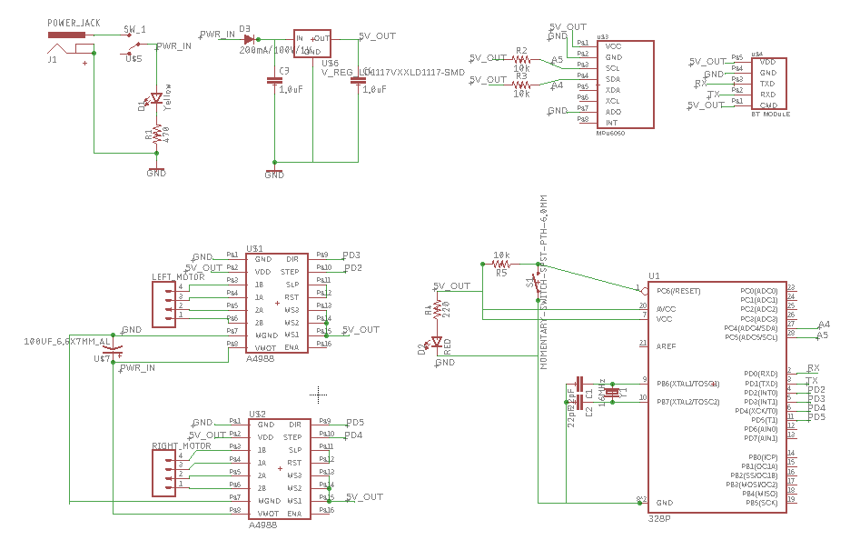
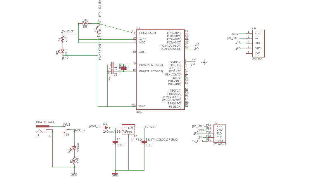
Figure 3: The
schematic view of the robot PCB.
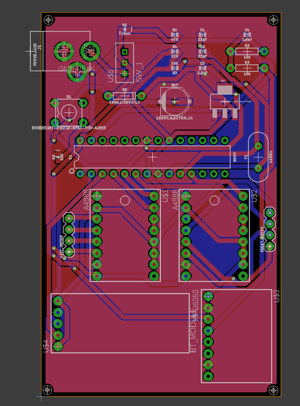
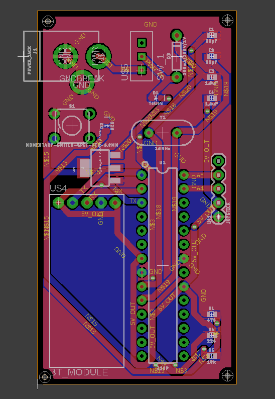
Figure 4: The layout view of
the robot PCB.
Figure 5: The
schematic view of the remote PCB.
Figure 6: The layout view of
the remote PCB.
The presentation on this project can be found here.
Discussion
It was very difficult to find the correct PID values. Once we found
them it balanced very well. However there was an unknown bug in the
wireless communication. You can see the robot trying to move in the
direction of the joystick in video 7, but it tries to balance which
cancels out the movement before it can move very far.