Introduction
The goal of this project was to create a prototype for a product that
reads acceleration and sends it wirelessly to a microcontroller which
records it on an sd card.
Methods
The accelerometer used was a MPU6050. It reads in acceleration data
into a master-configured ESP32. The master ESP32 sends the data
wirelessly to
another ESP32 in slave configuration. The slave ESP32 receives the data,
then writes it to a microSD card.
Results
Video 1: Basic LED blinking demonstration.
Video 2: Reading the accelerometer data and plotting it in Arduino.
Video 3: The acceleration data scaled to the +/- 4g range.
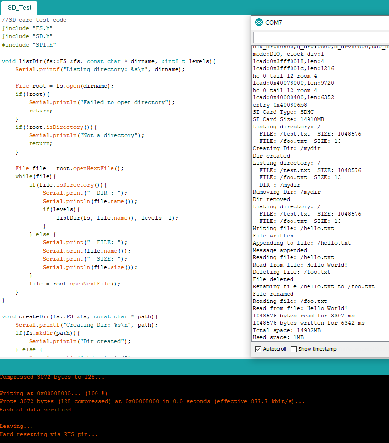
Figure 1: The ESP32 communicating with the SD card.
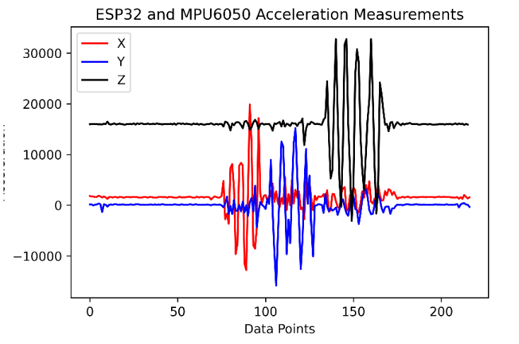
Figure 2: Data from the SD card plotted in python. The code to write
this data to the SD card can be viewed here.
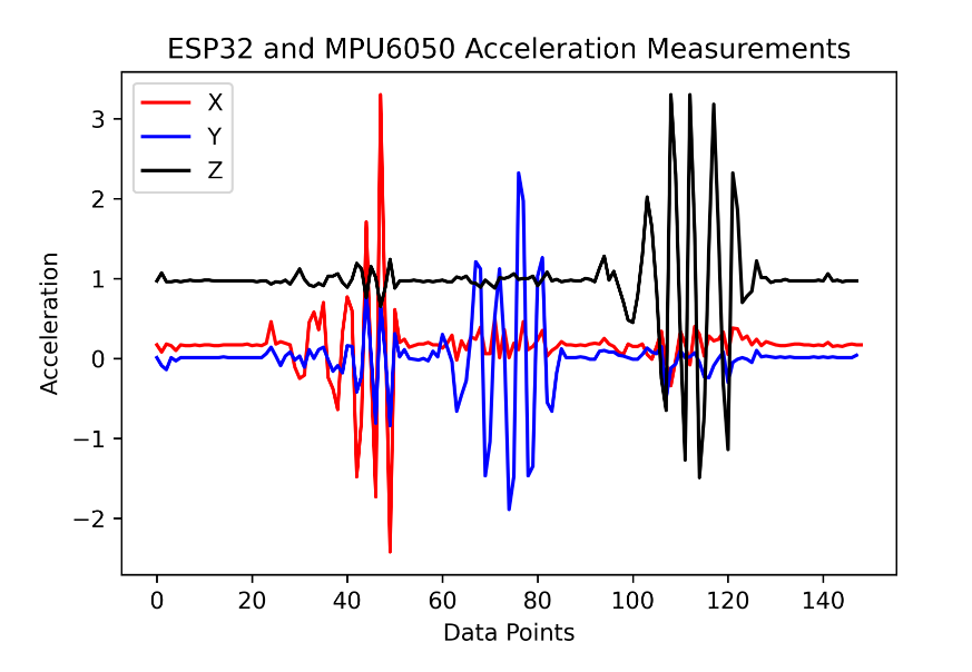
Figure 3: The data scaled to the +/- 4g range plotted in python. The code to
write the data to the SD card can be viewed here.
Video 4: Wirelessly sending the acceleration data from the master ESP32
to the slave ESP32.
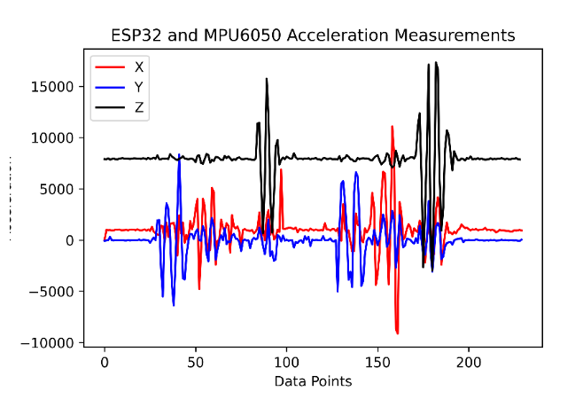
Figure 4: The data
transmitted wirelessly, written to the SD card, then plotted in python.
The cleaned up code for the master ESP32 can be found here, and the cleaned up code for the slave
ESP32 can be found here.
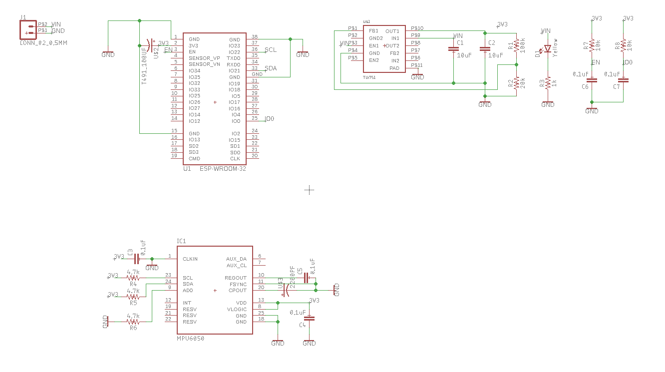
Figure 5: The schematic view of the PCB.
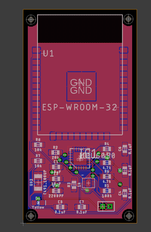
Figure 6: The layout view of the PCB.
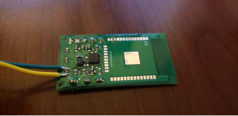
Figure 7: The pcb assembled with all the parts except for the ESP32.
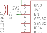
Figure 8: Pin 3 connected to EN on the schematic.
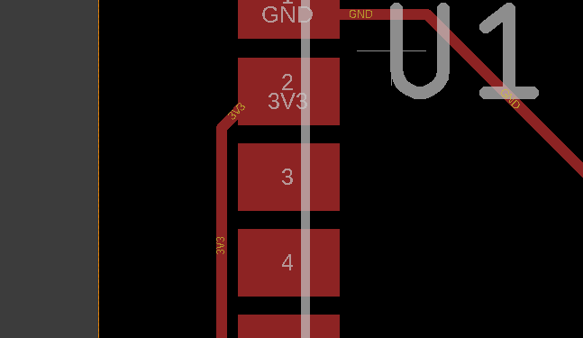
Figure 9: Pin 3 not connected to EN on the layout.
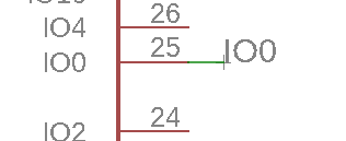
Figure 10: Pin 25 connected to IO0 in schematic.
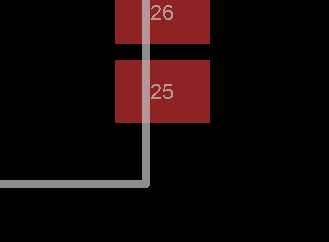
Figure 11: Pin 25 not connected to IO0 on layout.
Discussion The wireless
communication was not working at first. I believe this is
because I was only using one USB to power both the master and the slave
ESP32s. Once I plugged them both into USB, they were receiving enough
power and the wireless communication worked well. The PCB was not wired
correct so it would not work. When I looked at the design in Eagle I
noticed that the wiring looked correct on the schematic, but for some
reason left a few important thing unconnected on the layout. I'm not
sure how this happened, but I believe this is the reason my PCB was not
working. Even after deleting and reconnecting the pins in the
schematic, the layout would not recognize the connections. I am not
sure what I am doing wrong because I am using a technique that has
worked in the past.