Task 1:
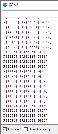
Figure 1: Red and IR lights in serial monitor.
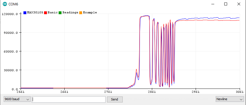
Figure 1.1: Red and IR reading in serial plotter.
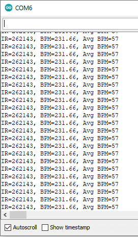
Figure 1.2: Measure heart rate (BPM).

Figure 1.3: Measuring Oxygen Saturation (SPO2).
Task 2:
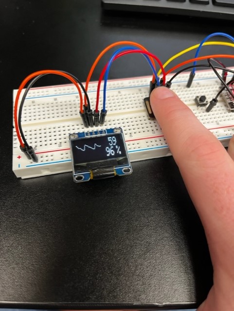
Figure 3: BPM wave form incorperated with the BPM and SPO2 measurments.
Fort Lewis College Technology Workshop
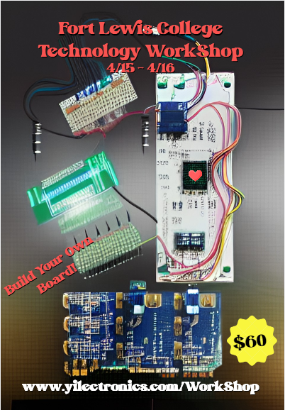
Figure 4: Flyer for the workshop.
Task 3:
Figure 3: BPM wave form incorperated with the BPM and SPO2 measurments.
Task 4:
Fort Lewis College Technology Workshop
Figure 4: Flyer for the workshop.
Conducted:
April 15 - April 16 from 9:30am - 3:30pm.
Students will participate in building various circuits from first understanding how to blink a led light to a more intrecate circuit. The final product of this workshop is to build up to the student creatign their own pulse oximeter. The students may take home their own pulse oximeter.
BOM:
The cost of materials for each students can be seen below in Fig 4.1. In order to make the kit less expensive I ordered in bulk for 10 students to participate instead of just 1 student. The cost per student is going to be $60. The profit from 20 students participating is $892.83.
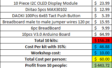
Figure 4.1: Bill of materials for 10 students participating.
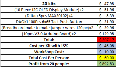
Figure 4.2: Bill of materials for 20 students participating.
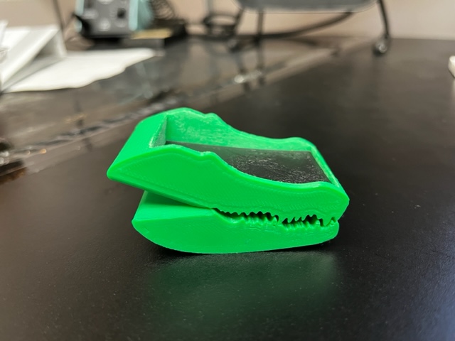
Figure 5: 3D printed alligator.
3D design of alligator
PCB Results
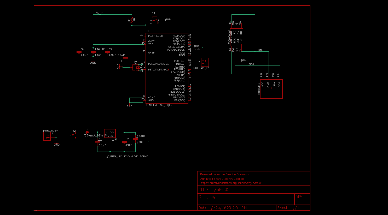
Figure 6: PCB schematic.
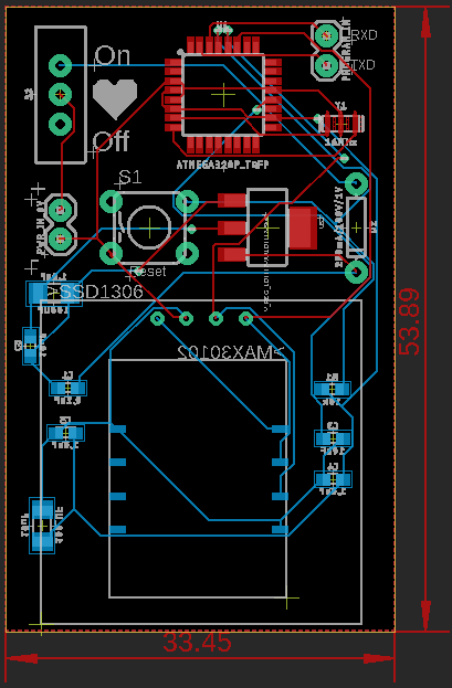
Figure 6.1: PCB layout.
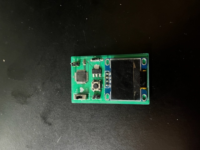
Figure 6.2: Top of soldered PCB.
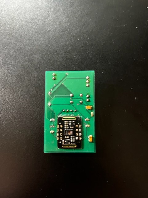
Figure 6.3: Back of soldered PCB
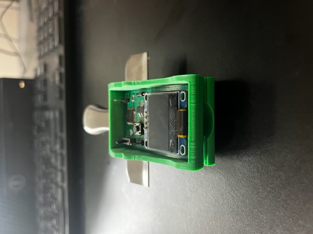
Figure 6.4: PCB inside housing front.
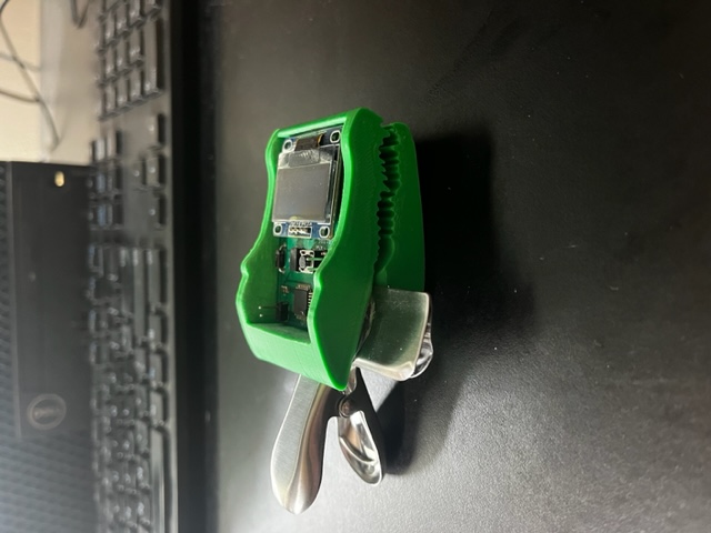
Figure 6.5: PCB side view.
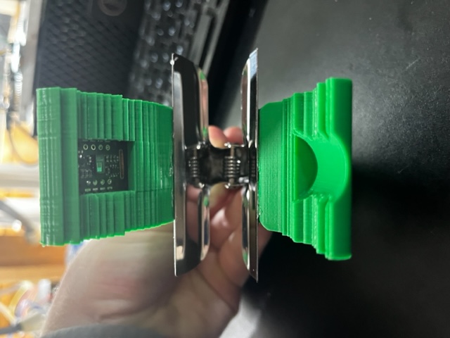
Figure 6.6: Inside the housing where the MAX310 can be seen.
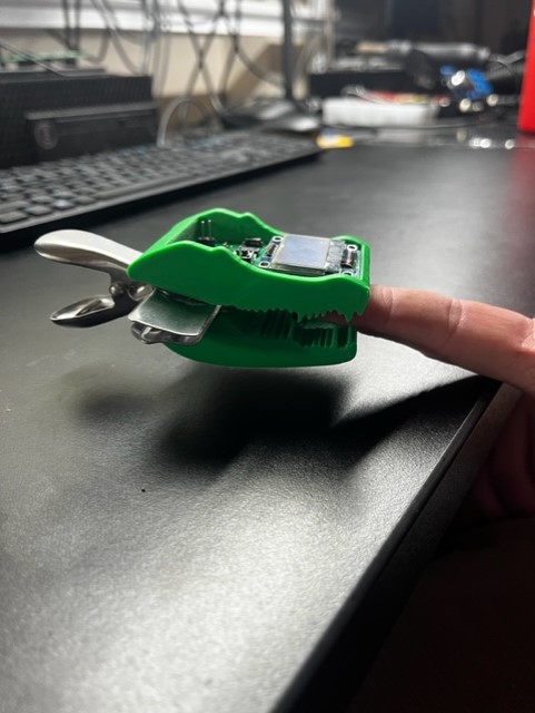
Figure 6.7: PCB on a finger.
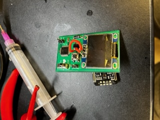
Figure 6.8: PCB fixed top.
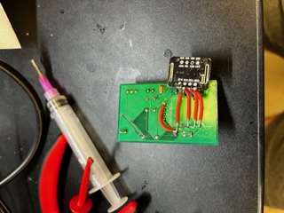
Figure 6.9: PCB fixed bottom
Students will participate in building various circuits from first understanding how to blink a led light to a more intrecate circuit. The final product of this workshop is to build up to the student creatign their own pulse oximeter. The students may take home their own pulse oximeter.
BOM:
The cost of materials for each students can be seen below in Fig 4.1. In order to make the kit less expensive I ordered in bulk for 10 students to participate instead of just 1 student. The cost per student is going to be $60. The profit from 20 students participating is $892.83.
Figure 4.1: Bill of materials for 10 students participating.
Figure 4.2: Bill of materials for 20 students participating.
Payment Method:
Task 5:
Figure 5: 3D printed alligator.
3D design of alligator
PCB Results
Figure 6: PCB schematic.
Figure 6.1: PCB layout.
Figure 6.2: Top of soldered PCB.
Figure 6.3: Back of soldered PCB
Figure 6.4: PCB inside housing front.
Figure 6.5: PCB side view.
Figure 6.6: Inside the housing where the MAX310 can be seen.
Figure 6.7: PCB on a finger.
Figure 6.8: PCB fixed top.
Figure 6.9: PCB fixed bottom
I had to go back through and wire around a couple of different things together but besides that it works well.