ENGR351 Lab 2020 Fall
Homework 3 - Advanced IoT Devices (ESP32)
Name: Ryan Jeanes
Email: rejeanes@fortlewis.edu
Sending Acceleration Data Between Two ESP32s
Introduction
For
a lot of projects that require gathering a lot of data points over a
long period of time, the ability to safetly store your data to use for
data analysis later is one of the most important parts of a
research project.
To demonstrate a way to do this, a circuit was created using 2 ESP32s, an MPU6050 accelerometer, and a microSD module.
Materials and Methods
The breadboard circuit consisted of 2 ESP32s, an MPU6050 accelerometer,
a microSD module, an Elegoo MB V2 power regulator, and 2 10K resistors.
The accelerometer functionality was tested, followed by testing the SD
card module, with the results shown in a video demonstration
and figure 1, respectively. Once both modules were proven to be
functional, then the ESP32s were coded to communicate the Accelerometer
data over ESP-now to be written to the microSD card for data analysis
using python. The code used for both the ESP32s and data plotting is shown here.
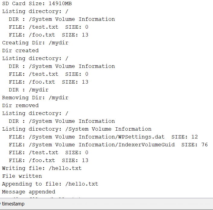
Figure 1 - SD card test
Results
The acceleration data was succesfully transmitted from the master ESP32
to the slave, and the slave ESP32 succesfully wrote each axis of the
acceleration data to the microSD card. The plots of the acceleration
data with unprocessed acceleration values and processed acceleration
values that range from -4g to 4g.
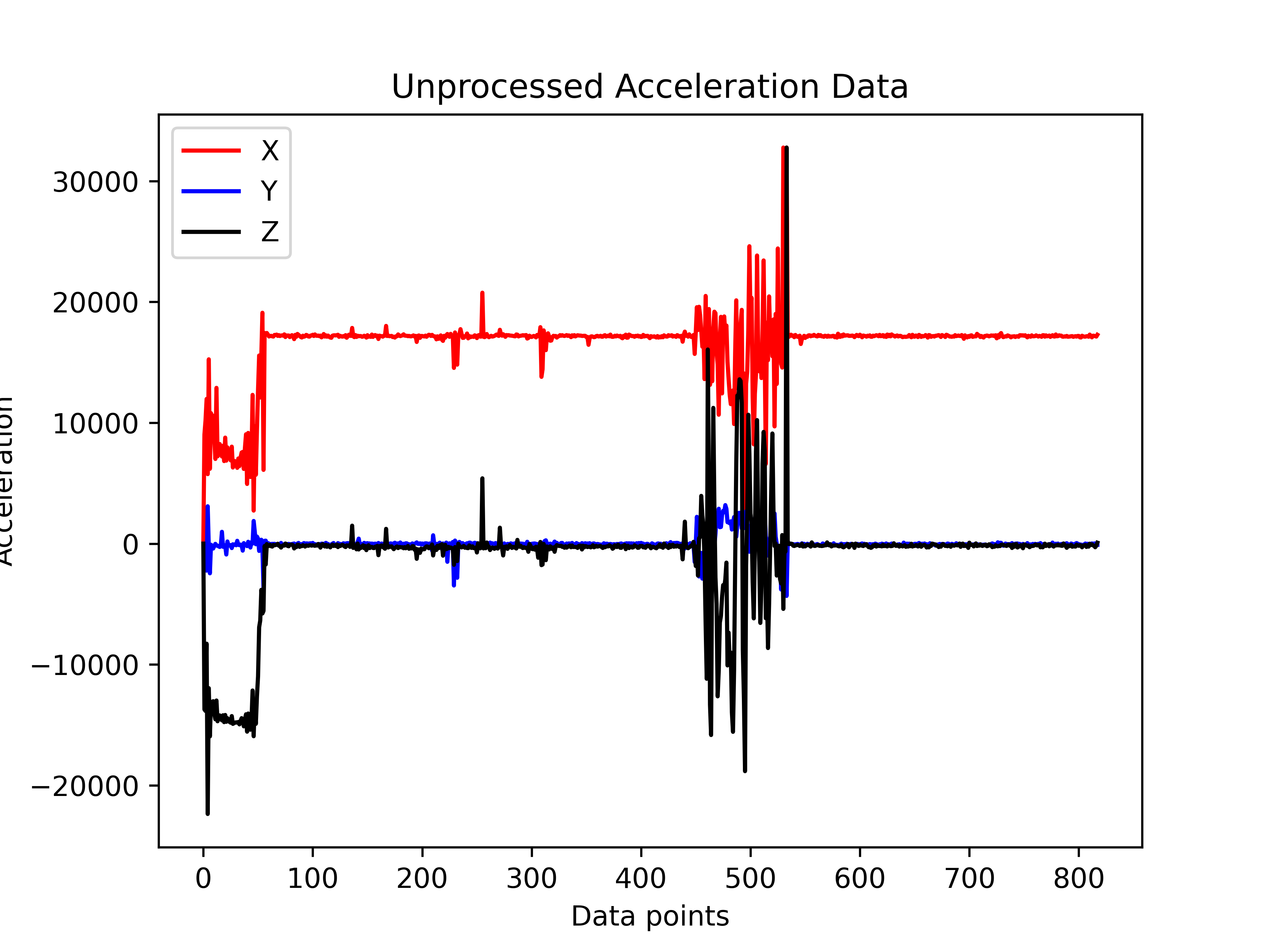
Fig 2 - Unprocessed acceleration data recorded from MPU6050
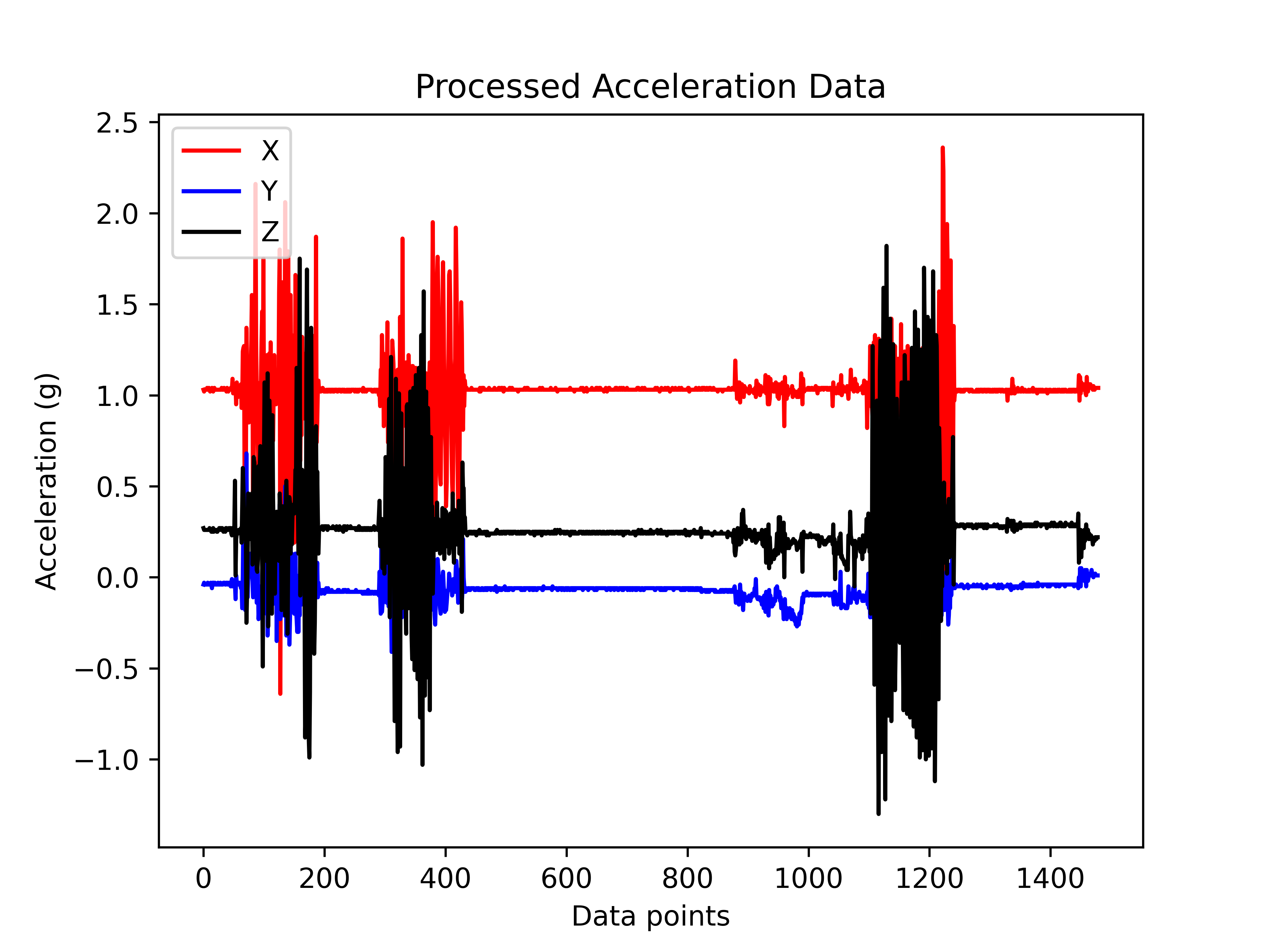
Fig 3 - Processed acceleration data recorded from MPU6050
Discussion
There was a minor
issue with the initial breadboard circuit, where powering both the
ESP32s with a USB cable was not providing enough current for the slave
ESP32 to function properly. Using an elegoo MB V2 power regulator fixed
this issue, and the ESP32s were able to function as expected.