ENGR338 Digital Electronics 2021 Spring
Lab 3 - Design R-2R Subcells
Name: Ryan Jeanes

Email: rejeanes@fortlewis.edu

Designing R-2R Subcells
Introduction
An important design aspect is splitting up common structures in circuits into subcells to make building larger components simpler and easier to troubleshoot or debug.
Methods
Using Electric VLSI, we created R_2R subcells schematic, icons, and layout for the R-2R ladder and created a new R-2R ladder comprised of these subcells.
Results
The subcells icons, schematic, and layout were all designed and cleared the DRC checks with only minor difficulties. However, the layout and schematic of the R-2R subcell isn't passing the NCC check for strange reasons. No matter how the schematic is structured, or restructered, or even deleted and rebuilt all of the R-2R subcell schematic and layouts Electric VLSI seems incapable of recognizing that there are 3 export nodes in the R-2R subcell schematic. Because of this, the simulation showed somewhat of a step-function with the output, but it was heavily distorted and not outputting proper voltages. I have a sneaking suspicion that my installation got corrupted somehow, as the DRC check was originally crashing instead of reporting errors. Unfortunately, there wasn't enough time left to reinstall and potentially rebuild the entire library if that did not fix the odd behavior.
subcellSchematic
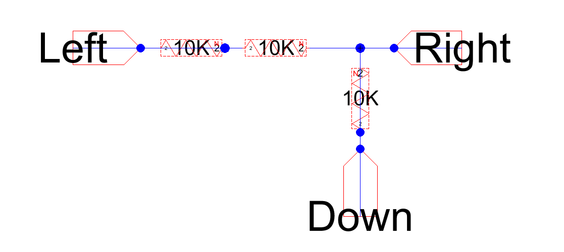
Figure 1 - R-2R subcell schematic
subcellLayout
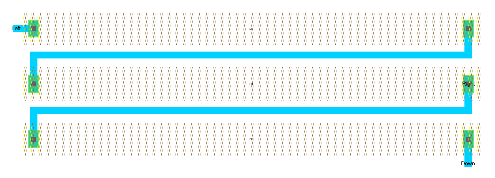
Figure 2 - R-2R subcell layout using n-well resistors of 187.5 lamba width
subcellIcon
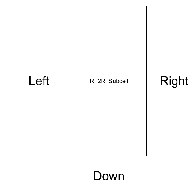
Figure 3 - R-2R subcell icon
NCCerror
Figure 4 - NCC error reporting Left and Right exports don't match any exports in the R-2R schematic, despite there verifiably being both Left and Right exports in the R-2R schematic