ENGR338 Digital Electronics 2021 Spring Lab 2 - Design an R-2R DAC
Name: Ryan Jeanes Email: rejeanes@fortlewis.edu
Designing an R-2R DAC
Introduction The R-2R DAC ladder directly
converts a parallel digital signal into an output voltage, using simple
voltage division. Because of this, it can be easily scaled to any
voltage. In order to analyze an R-2R ladder, you only need to use
simple superposition and equivalent circuits to be able to calculate
the output voltage according to how many bits are high. In order to
show how a digital signal is translating using this DAC, we are
designing one in ElectricVLSI and using LTSpice to simulate the
circuit. Methods Using
ElectricVLSI, we simulated an ideal 10-bit ADC connected to an ideal
10-bit DAC to view the voltage output compared to the input. Then, we
designed a 10-bit R-2R DAC to replace the ideal 10-bit DAC to be able to
see the difference in voltage output. Afterwards we then connected pins
B0-B8 to ground on the 10-bit DAC and used a pulse function on the B9
pin to see how the R-2R DAC drives a 10pF capacitor. Results Our test
simulation with the Ideal 10-bit ADC to 10-bit DAC circuit ran without
issue. After substituting the R-2R ladder, the circuit was then
simulated again to compare the difference. In order to use the R-2R
ladder in the simulation we had to include a ground pin in the icon for
the LTSpice code to recognize the Vout line, as by default it kept
marking the line as Vout/GND. The final task, seeing how the DAC drives
a 10pF capacitor, unfortunately, wasn't completed. The LTSpice
simulation would not recognize the Vout line like it did in previous
simulations, and after completely rebuilding the icon and
double-checking the
schematic for the R-2R DAC, the Vout line still wouldn't be recognized.
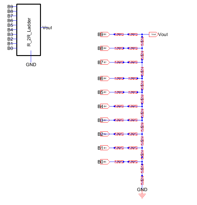
Fig 1 - 10-bit R-2R ADC schematic built in ElectricVLSI
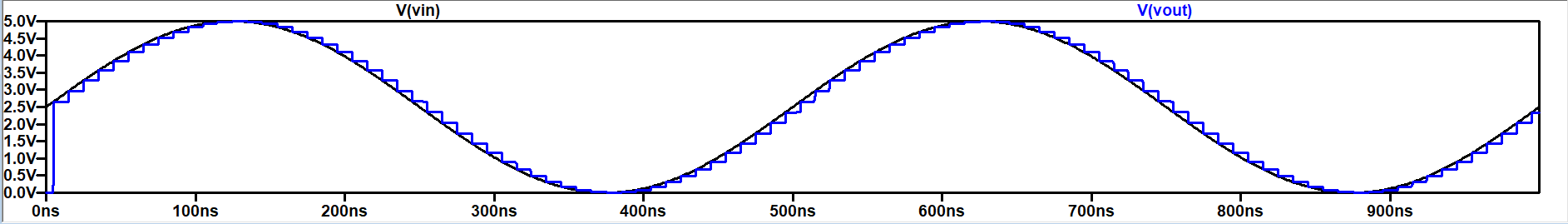
Fig 2 - LTSpice output for ideal 10-bit DAC
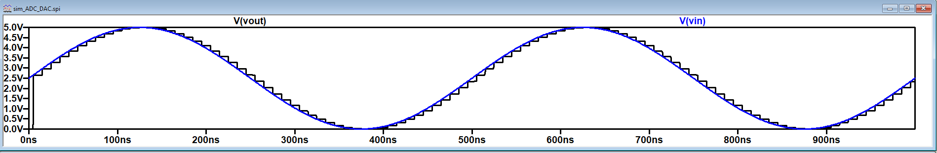
Fig 3 - LTSpice output for 10-bit R-2R ADC
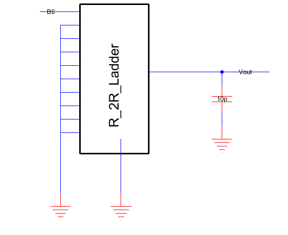
Fig 4 - Circuit where R-2R ladder is driving a 10pF capacitor, using a pulse function for pin B9