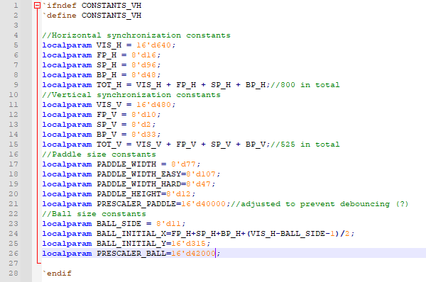
Figure 1 - Verilog header containing constant definitions used across most of the files.
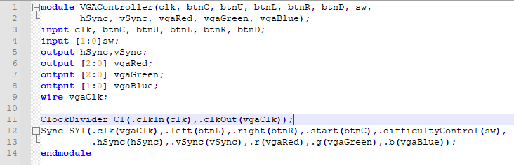
Figure 2 - Top module code
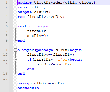
Figure 3 - Clock divider using 2 flip flops to divide the 100MHz input 4 times, outputting approximately 25MHz that was used as the VGA clock.
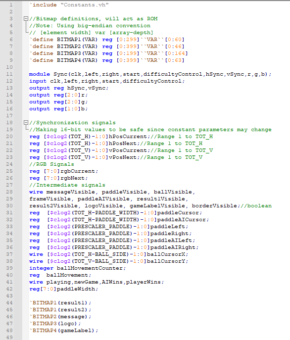
Figure 4 - Port and register definitions for Sync.v
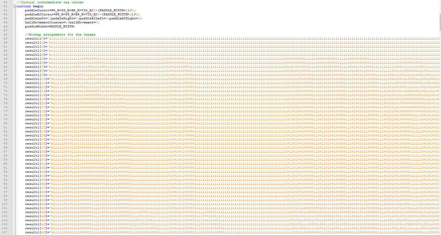
Figure 5 - Initial states of bitmaps and registers. The bitmaps are all initialized as shown, since Verilog doesn't allow block assignment for 2D memory.
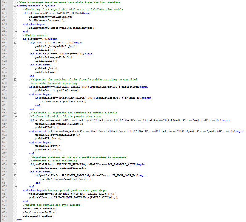
Figure 6 - Logic control in Sync module that determines the next state of the program.
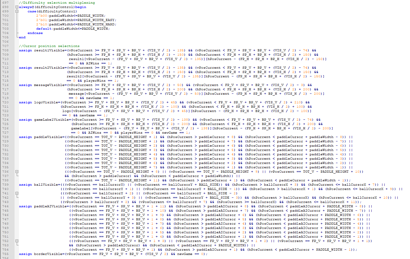
Figure 7 - Multiplexer for difficulty selection as well as logic control for what bitmaps are visible on screen.
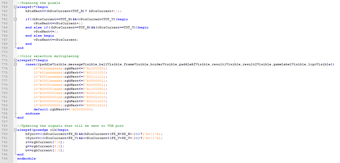
Figure 8 - Code controlling VGA output. First block scans the pixels while the multiplexer selects an 8-bit color for the selected pixel position depending on if it overlaps any of the labels, logos, paddles, or ball.
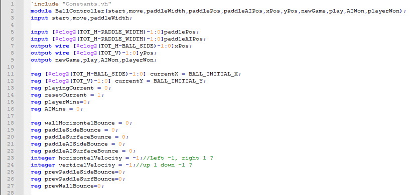
Figure 9 - Port and register definitions for the BallController module.
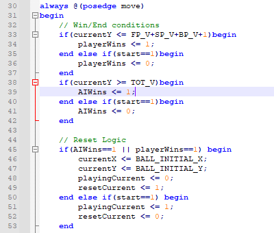
Figure 10 - BallController.v Win/End conditions for the game, all logic in this module updates on posedge of move clock.
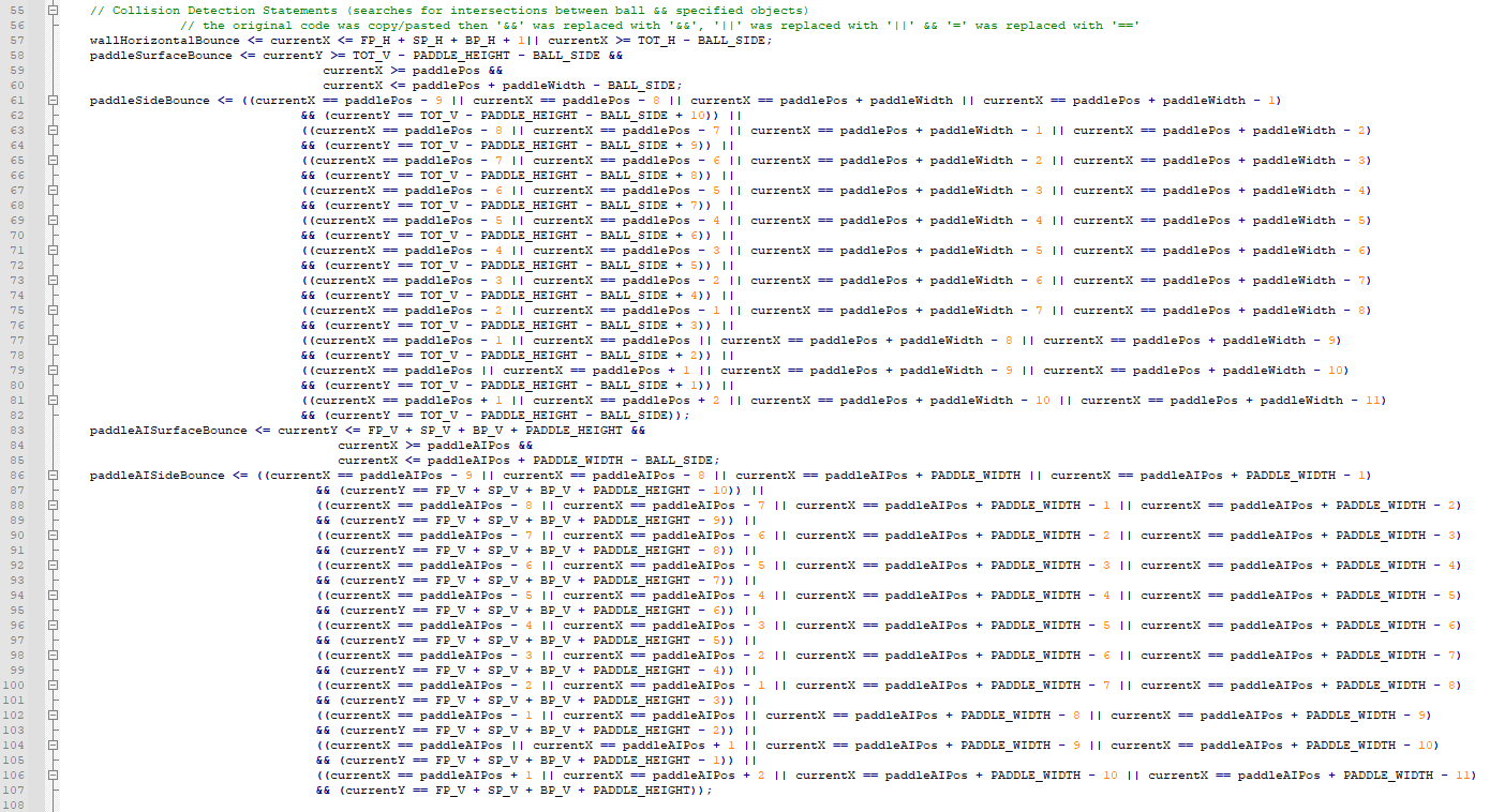
Figure 11 - BallController.v collision logic. Player paddle surface collision needs adjustment somewhere, but not sure what exactly the adjustment needs to be as of now.
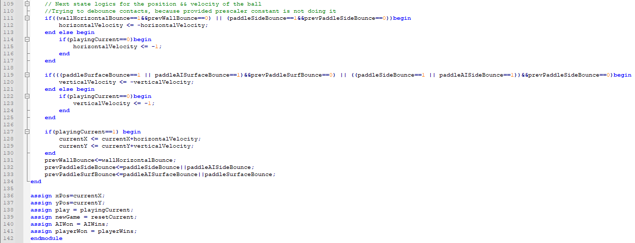
Figure 12 - BallController.v velocity direction logic, had to add extra to help debounce the ball collisions. Otherwise, the ball gets stuck along the wall or AI paddle.
Discussion
The debouncing is the biggest problem in the code still. After trying several methods, the problem still persists. Due to the nature of the program it is difficult to tell whether the issue lies with debouncing, which some methods to fix suggests yes, or if the problem lies with detecting the ball collision itself. Since we used the exact same logic initially, it may be that VHDL is doing something behind-the-scenes that verilog does not or this is simply a result of how Verilog gets written onto the Basys 3 board compared to VHDL. However, this doesn't quite explain why, despite using the same detection logic, the ball does not detect a collision with the player paddle's surface (but it does detect collisions with the side of the player's paddle, interestingly). The problem was slightly relieved by increasing the clock cycle that drove the ball movement and collision detection, however the resulting slow-down of the ball movement itself would make the game be a bit too trivial. Though, despite these increases, the ball would not detect a collision with the AI paddle. Due to previous test runs, we do not believe the actual paddle boundary itself is the issue, but considering the odd behavior of the player paddle surface detection it is possible that this is the case. Our latest build included a debounce module to be used to debounce the collision Initially, we presented that we changed the RGB output to the 8-bit 3-3-2 format, but this change was reversed to the original 12-bit 4-4-4 RGB format as the VGA output being out of sync was the sole issue for not being able to display the game on the screen.
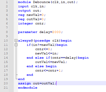
Figure 13 - Debounce module implemented to attempt to correct velocity changes and collision detection.
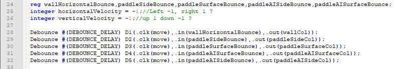
Figure 14 - The debounce modules being implemented, as well as the intermediate values that are used to debounce.
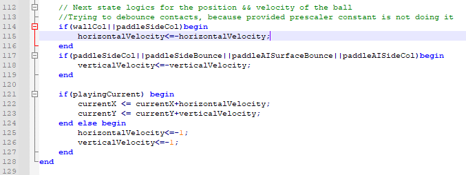
Figure 15 - The revised logic using the intermediate values shown in Fig. 14.