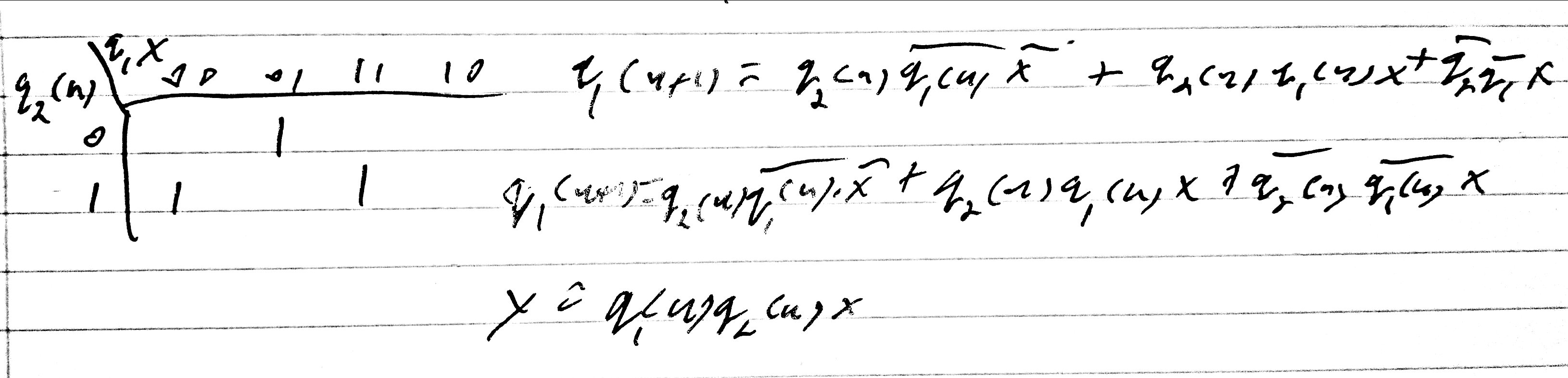
Figure 1 - Equations for state table given in section 1, with q1(n+1) derived from k-map.
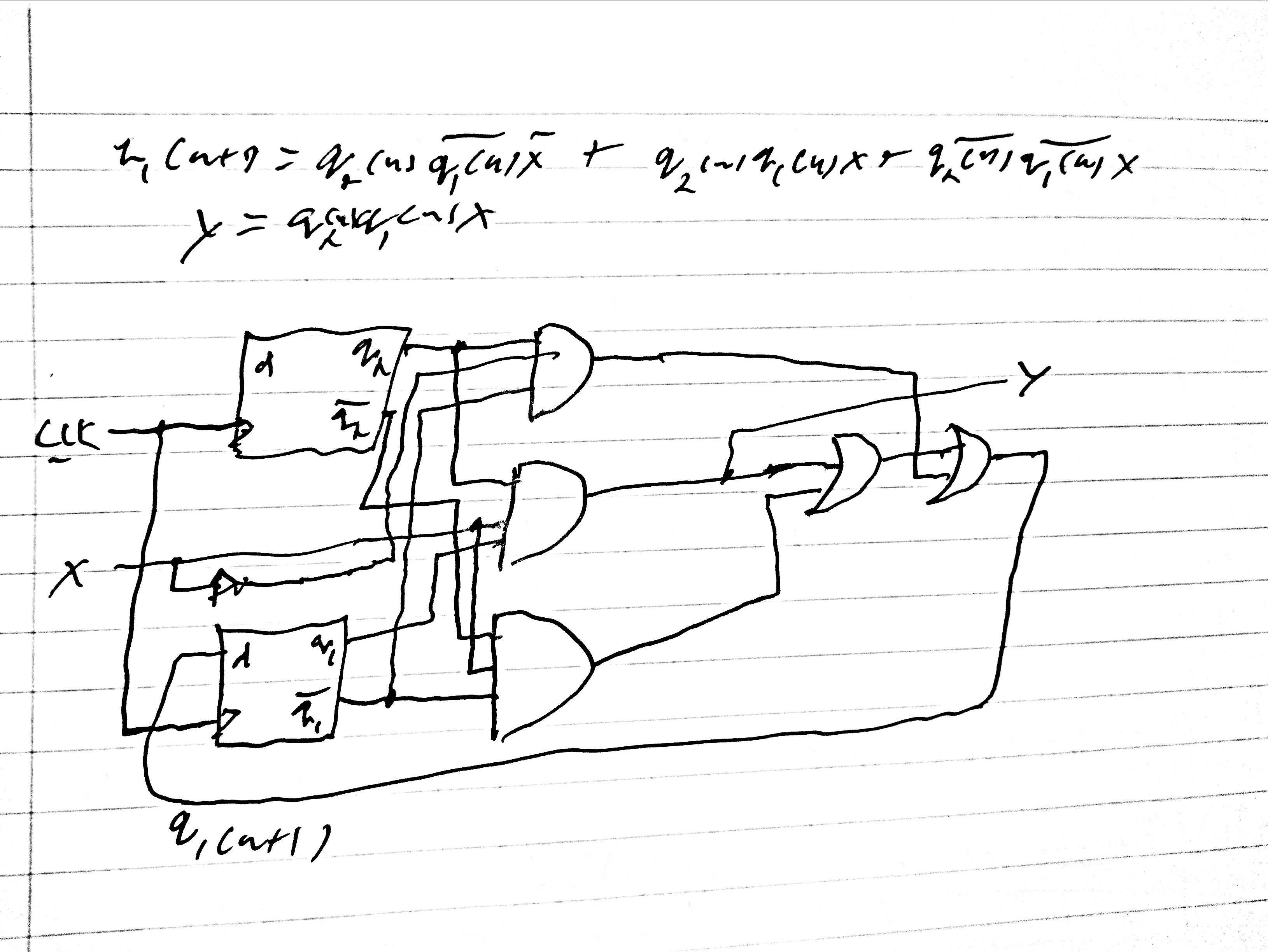
Figure 2 - Drawn circuit derived from the equations.
Task 2
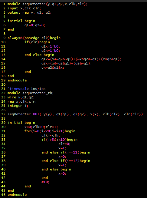
Figure 3 - Code for sequential detecter shown in section 3
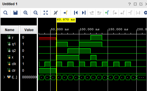
Figure 4 - Simulation for sequential detecter
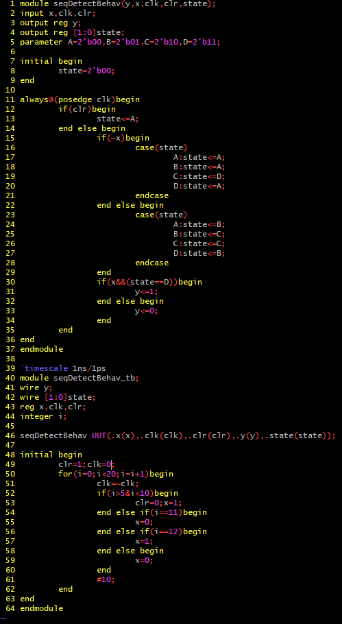
Figure 5 - Code for sequential detecter using behavioral modeling
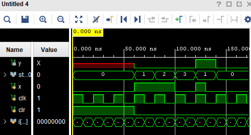
Figure 6 - Simulation for sequential detecter using behavioral modeling
Task 3
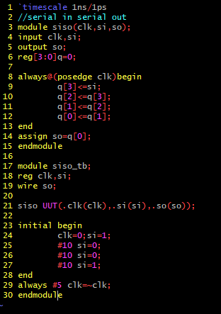
Figure 7 - Code for SISO register
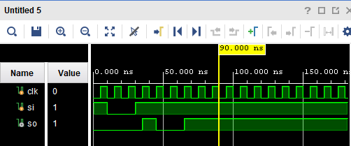
Figure 8 - Simulation for SISO register
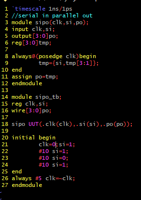
Figure 9 - Code for SIPO register
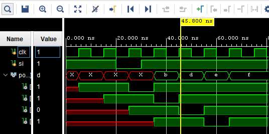
Figure 10 - Simulation for SIPO register
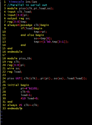
Figure 11 - Code for PISO register
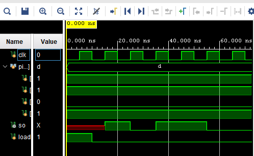
Figure 12 - Simulation for PISO register
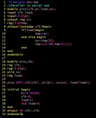
Figure 13 - Code for PIPO register
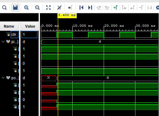
Figure 14 - Simulation for PIPO register
Figure 7 - Code for SISO register
Figure 8 - Simulation for SISO register
Figure 9 - Code for SIPO register
Figure 10 - Simulation for SIPO register
Figure 11 - Code for PISO register
Figure 12 - Simulation for PISO register
Figure 13 - Code for PIPO register
Figure 14 - Simulation for PIPO register
Task 4
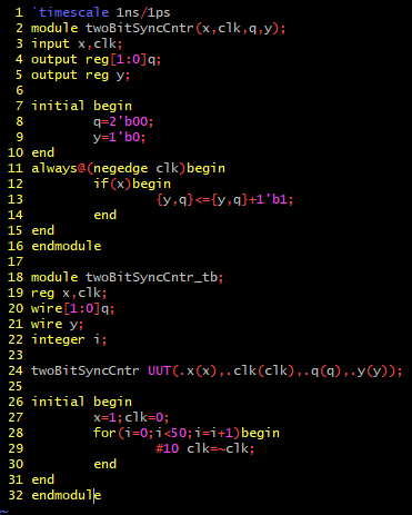
Figure 15 - Code for two bit synchronous counter
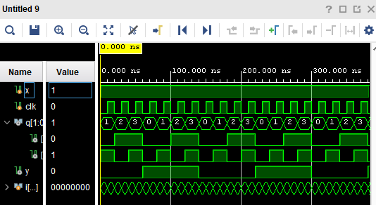
Figure 16 - Simulation for 2 bit synchronous counter
Figure 15 - Code for two bit synchronous counter
Figure 16 - Simulation for 2 bit synchronous counter
Task 5
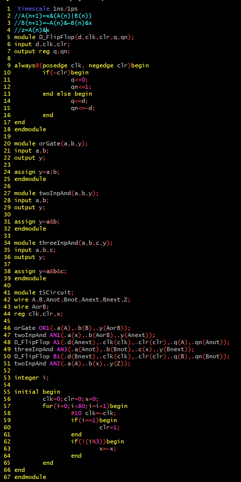
Figure 17 - Code for the given circuit, with derived equations in the commenting
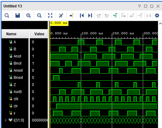
Figure 18 - Simulation for the modeled circuit.
Figure 17 - Code for the given circuit, with derived equations in the commenting
Figure 18 - Simulation for the modeled circuit.