CE433 Embedded Devices Spring 2022
Homework 11 - SPI
Name: Ryan Jeanes
Email: rejeanes@fortlewis.edu
Homework 11 - SPI
Introduction
This
assignment introduced how to use the SPI protocol on the basys 3 board
in order to read data from a light sensor and display it on the
7-segment display.
Results
AThe
only BCD value I was able to receive from the sensor was 0031, no
matter how much light shone on the sensor or lack thereof. However, I
do not believe this issue is caused by the circuit logic to display the
BCD values on the board, because when the sensor is removed the
displayed value changes to 0255, as expected. These BCD values also
match the untranslated values being received from the sensor, as well.
Task 2
Here is the demonstration video. (Reuploaded this, since for some reason the video's processing failed without me realizing it).
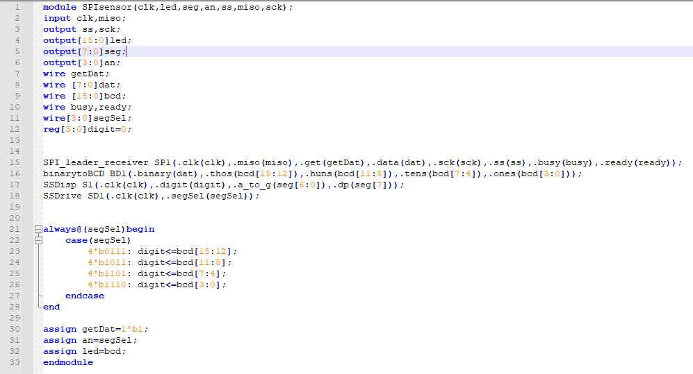
Figure 1 - Top module, includes multiplexing for deciding which digit to display depending on which segment is selected.
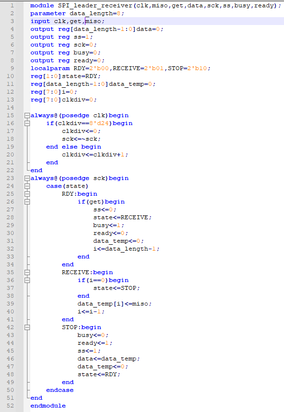
Figure
2 - SPI receiver. Tried to flip sck on both clkdiv==8'd25 as provided
in the example and 8'd24 as in the book. Neither changed behavior.
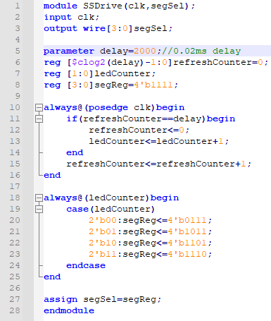
Figure
3 - The driver for the seven-segment display. Switching lit segment
every 0.02ms, which resulted in being unable to perceive the blinking
at longer delays.
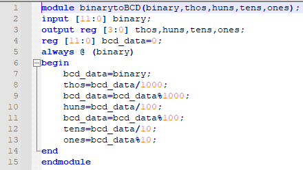
Figure 4 - Provided binary-to-BCD verilog file, with no changes made.