CE432 Robotics II Fall 2022
Homework 7 - ESP32 CAM Soldering
Name: Ryan Jeanes
Email: rejeanes@fortlewis.edu
Homework 7 - ESP32 CAM Soldering
Introduction
For this assignment, we integrated our PCB designs into the cars we built.
Design
The PCB for the car includes connections for the ESP32-CAM board, headers for the 6 outputs to control the motors, 5 pins for serial and
grounding the IO0 pin to allow for uploading code to the board, and a mount for the LM2596 voltage regulator. There is a connector for
12V input that only feeds to the LM2596. Since the schematic I found wasn't super clear for the dimensions, I included
a connector for 5V input so that the board can still be powered should the custom footprint not fit the LM2596.
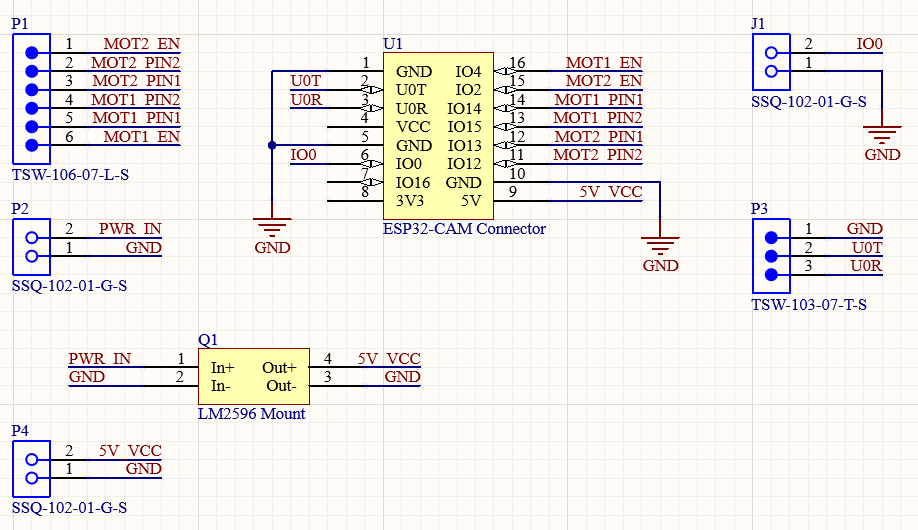 Figure 1
 - Schematic for PCB used to control the car.
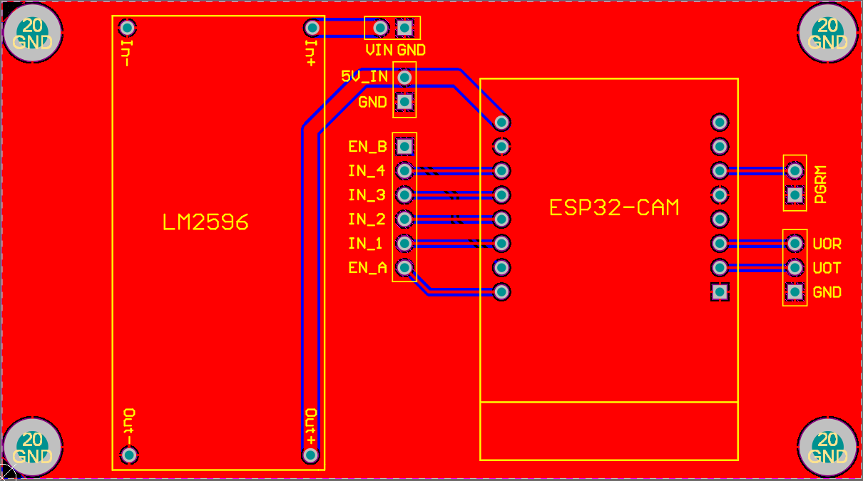 Figure 2
 - PCB layout.
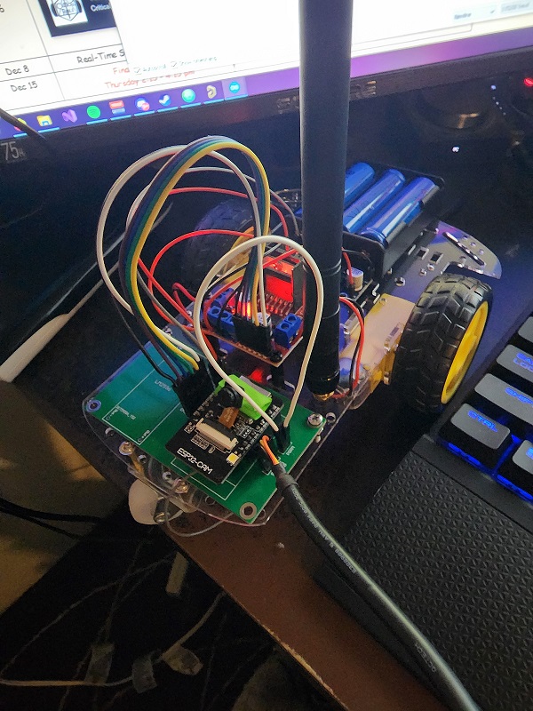 Figure 3
 - Photo of the assembled car connected to USB.
Results
The car is able to create the webserver and be controlled by pushing the buttons. The car accelerates and decelerates by incrementing/decrementing
the output on the A and B motor EN pins with a 5ms delay between each step. I attempted to have the stream rotated, which works fine on
the desktop, but on my mobile phone, which is what I will use for the demo, the stream blocked the buttons. Trying to float or align both the buttons
and stream images to certain areas didn't fix this issue, and I do not know enough HTML or css to fix this issue.