CE432 Robotics II Fall 2022
Homework 5 - Joysticks
Name: Ryan Jeanes
Email: rejeanes@fortlewis.edu
Homework 5 - Joysticks
Introduction
For this assignment, we are learning how to read input from a joystick and how to drive a stepper motor driver. Since I didn't have any Arduino Unos, I opted to use 2 Arduino Nanos since they both have the same ATmega328 processor.
The stepper motor driver used was the A4988, a NRF24L01 2.4GHz Transceiver was used for communication between the Nanos, and the stepper motor used was a NEMA17 bipolar stepper motor. The stepper motor used was one I owned that was
used for my senior sem project, since it is also NEMA17 with what I assume to be near identical power specs.
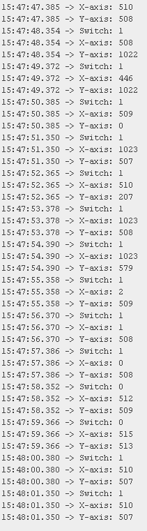
Task 1
Task 1 was completed succesfully, and encountered no issues.
Figure 1 - Screenshot of input read from the joystick.
Task 2
So, this part of the assignment is where I was reminded that I have the worst luck imaginable. I opted to go with the Nano because
I knew I had at least one Nano at home, so I only needed one from the lab. Now, the one from the lab I got worked, but I had issues
uploading code to the one I had at my house Tuesday. So, Wednesday (today) I was able to grab 2 Nanos from the lab that way I
had an extra in case one of them didn't work. However, neither of those two nanos work. I am certain of this because the one Nano that
worked did so when connected to either the receiver or transmitter side of the circuit.
After hours of testing and debugging them I am unable to answer why, as none of them passed a loopback test (Including my own Nano and the one of the three I got from the lab that works).
It turns out that of them all are clones made by some third party that use a CH340g USB to TTL converter IC instead of the ATmega16U2 of the original design. For these clones the
RX/TX traces are connected differently to the LEDs than the original's ATmega16U2's RX/TX traces were connected. For the CH350g, there is a 1K resistor and LED
connected to the RX/TX that is driven exclusively by the RX/TX lines, while the original's ATmega16U2 had 2 separate pads to drive the RX/TX LEDs. I think
this is the reason why the loopback test is failing, as I'm willing to bet those resistors are sinking enough power that shorting the RX/TX lines for the
loopback test will not work. You can still see the LEDs flash, but that isn't enough to let you know whether or not the serial data is being malformed in some way.
I also tried using the working Nano to burn new bootloaders on the two I got from the lab that were not working. However, I was unable to do so which leads me to believe that some of the
pins are likely damaged as one of them actually uploaded code appropraitely but was failing SPI communication with the NRF24L01 where the one working Nano operated perfectly. This, with
the fact that burning a bootloader onto a Nano uses another Nano uses SPI leads me to think that's where the issue is one of them. The other, however,
I could not upload code nor burn a bootloader. The one stroke of luck I had is that I was able to burn a new bootloader on the one Nano I had that originally also didn't work, and it worked perfectly with the code uploaded, which
meant its only issue was likely just a corrupted bootloader.
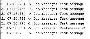
I was able to test that the two working Nanos were able to send/receive messages, for which they succesfully did. The one thing I noticed is that
there was occasionaly quite a bit of downtime between the receiver properly catching messages despite the sender sending messages on a 1 second interval. I am unsure
if this is an artifact of the RadioHead library I was using for the NRF24L01 or if there was some issue with the receiving controller as I did not want to risk breaking everything
by trying to explore either possibilities (I had initially hoped to have this done by 3:30-4:30PM as the code itself only took me about 10-15 minutes to write for all the tests and the
final code).
Figure 2 - Screenshot of the Serial Monitor when testing that the transmitting and receiving Nanos are both sending/receiving messages appropriately.
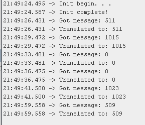
Figure 3 - Screenshot of serial monitor showing data received when testing both receiving and
converting the Y-axis readings sent by the sender.
Task 3
For the final task I didn't make any changes to the sender code from the test code beyond adding preprocessor statements so that the
code relating to the debugging prints didn't compile as the sender would not be connected to the serial monitor. On the receiver's
end I wrote a short function to convert the received c-style string to an unsigned int, and instead of using delays I used the
8-bit internal Timer 2 to control the pulses being sent to the A4988 driver. This method worked quite well to drive the stepper motor, and
I believe the timer can be set in Phase Corrected PWM mode or Fast PWM mode to drive the motor without using the extra memory on a bool variable but
I did not have enough time to get that working properly.
This demo had the same issue I had in the previous task with the receiver occasionally taking several seconds after succesfully receiving
a transmission before being able to accept another transmission. This wasn't consistent, sometimes there was only about a second in between while
other times it was as long as 7-8 seconds between received messages.