1. Project
2. The purpose of this lab is to design an esp 32 module
using eagle creating the schematic and layout. Then once the board is
recieved soldering all nessasary smd devices to power module. Then the
module will be attached to a 3.7 lipo batter to provide voltage to esp
and a circuit will be created to power the lipo battery using a power
regulator, charging module and switches. Lastly the esp 32 pcb will be
tested to verify functionality.
3. Materials and Methods
ESP32
lipo 3.7 battery
charging circuit
4. Results
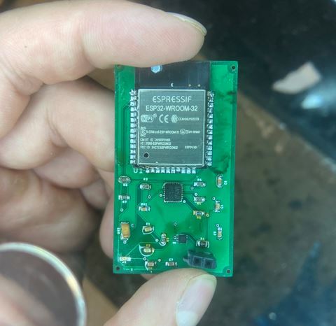
Figure 1. Task 1 soldered board will all nessasay devices.
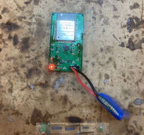
Figure 2. Task 2 device is being powered by the 3.7 lipo batttery.
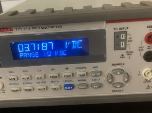
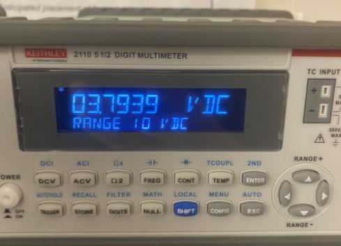
Figure 3. Battery multimeter reading before when uncharged then added
switches flipped and allowed to charge voltage. (task 3)
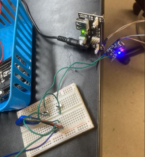
Figure 4. Entire charging circuit connected the PBC
Figure 5. Light turns on when switches allow battery to be connected to charging circuit allowing charging to occur.
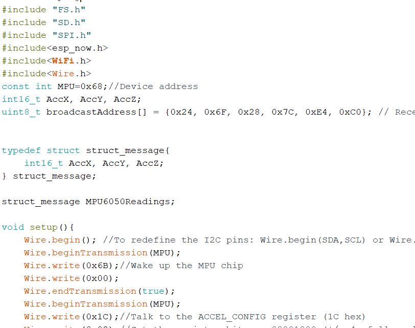
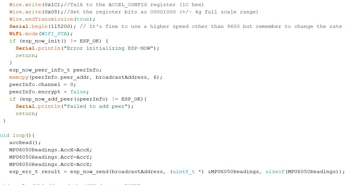
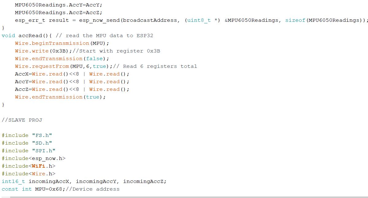
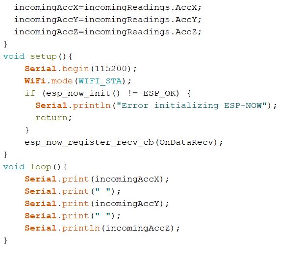
Figure 6. Code used to demonstrate task 4 the functionality of the sensor board and the display. (task4)
Figure 7. Demonstration of PCB (not yet achieved)
5.
Discussion
The lab was good overall there was some stuggles with soldering and
functionality of the power supply. These were remidied with resoldering
carefully and makeing sure things werent being shorted. The Lab was
challanging at times but good to know the knowledge here and the lipo
battery was a cool modification.