1. Combonational Logic Blocks
2. The purpose of this lab was to simulate the Half Adder and
Full Adder, design the testbench for the comparator with simulation,
design the testbench for the 4-bit comparator with simulation,
implement a 2-bit comparator on the Basys 3 board, design the testbench
for the decoder and verify the logic in simulation. Similarly, to
design a 8x3 priority encoder, find Q2 and Q1 verify the logic with
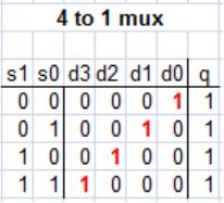
simulations, implement a 4-1 multiplexer on your Basys 3 board, verify
an even parity generator and checker in simulation respectively and
implement an even parity checker on your Basys 3 board. Lastly,
implement the improved car parking spot count and improved home alarm
system on Basys 3 board.
3. Materials and Methods
GVIM computer
Application
Paper and Pencil
Vivado Application
4. Results
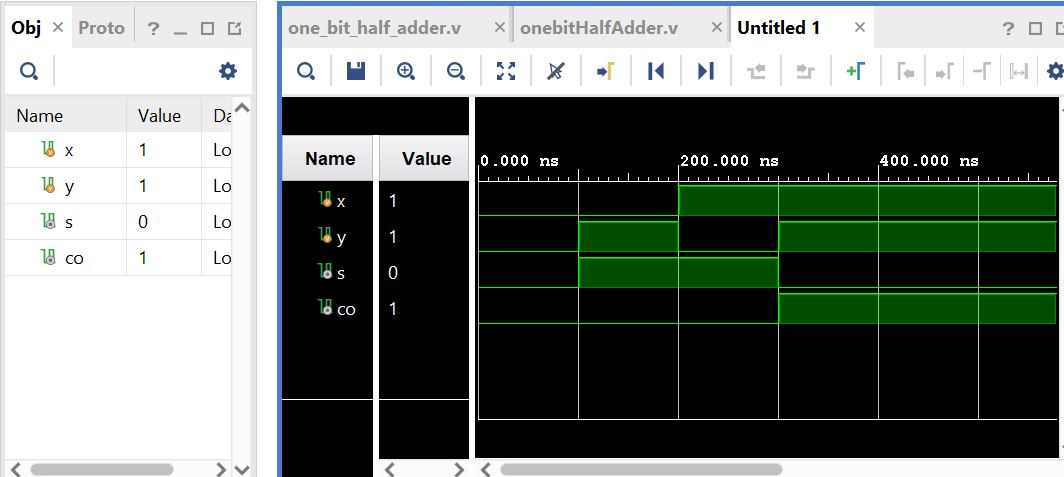
Figure 1. Half Adder Simulation using test bench and verilog.
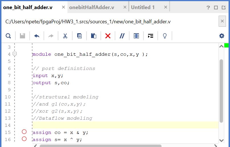
Figure 2. Half Adder verilog Code Part one.
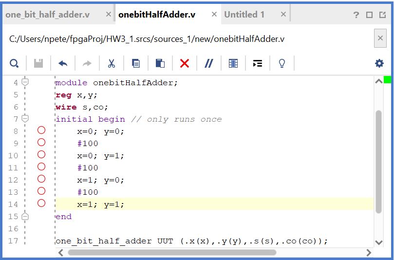
Figure 3. Code
for half adder simulation using Vivado part 2.
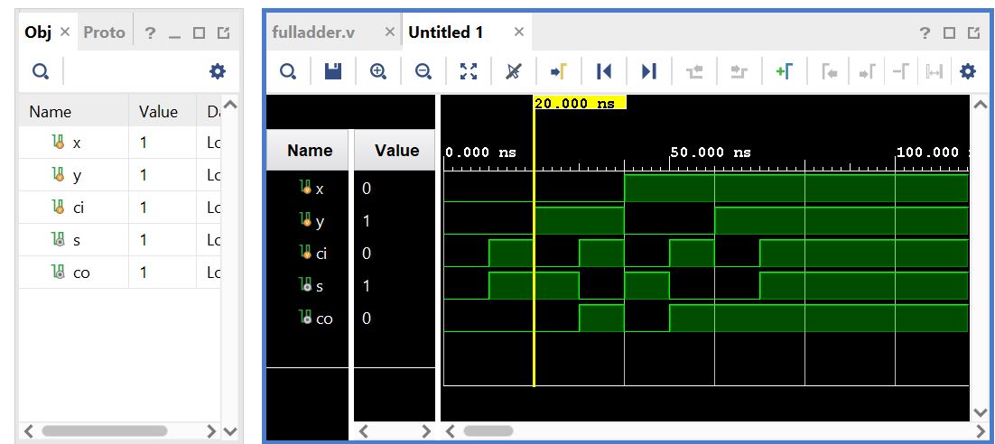
Figure 4. Full
adder simulation shown using a created test bench.
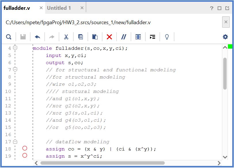
Figure 5. Full Adder code shown using verilog Part 1.
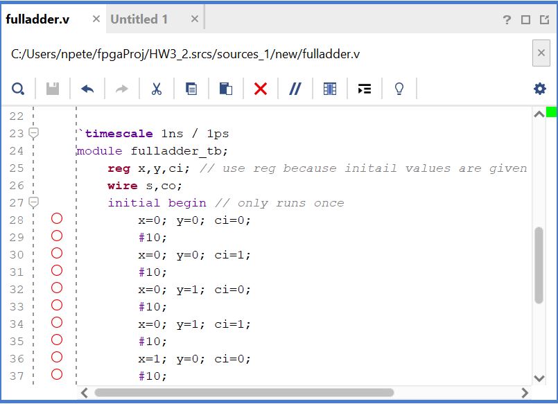
Figure 6. Full adder code using verilog and fashioned testbench Part 2.
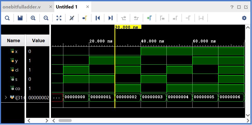
Figure 7. Full Adder using different method using a counter in test
bench.
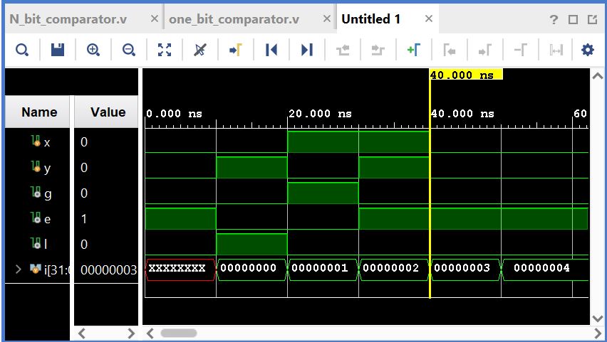
Figure 8. One Bit Comparator design with a test bench
displaying the logic.
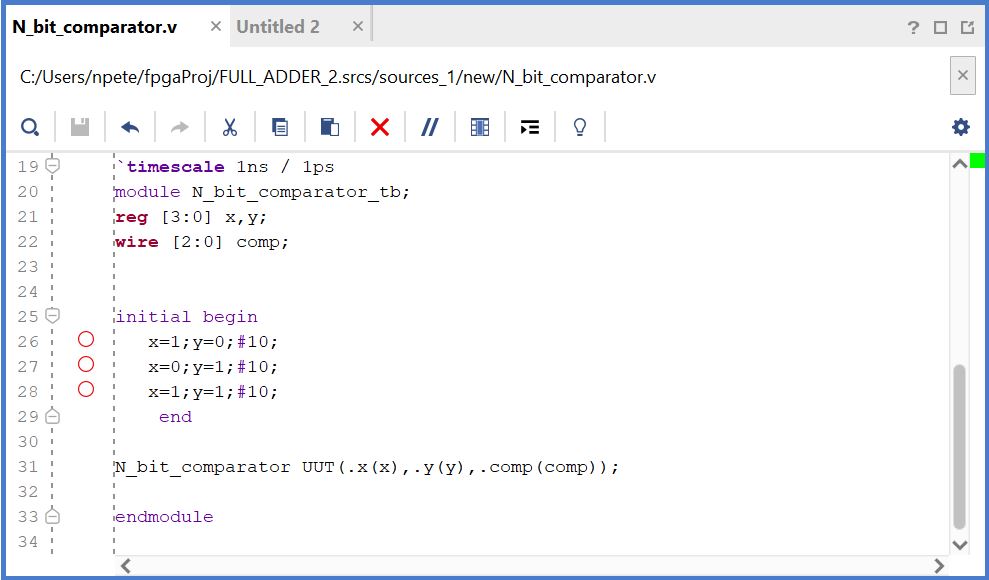
Figure 9. 4 bit comparator test bench for simulation results.
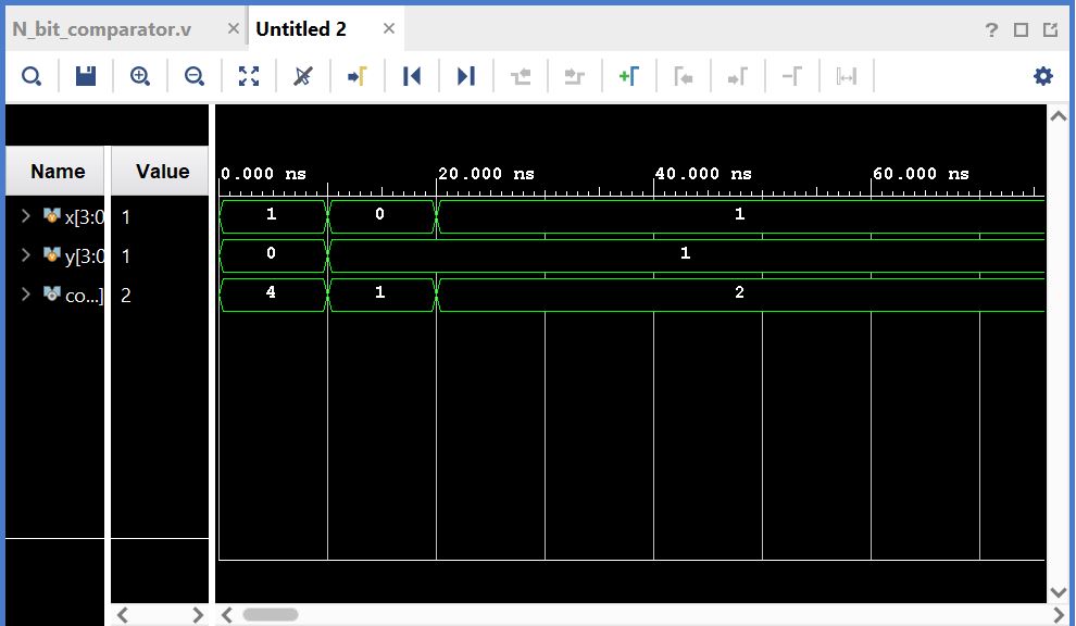
Figure 10. 4 bit comparator simulation shown displaying a certain
number when comparator logic is reached.
Figure 11. 2 bit comparator simulation shown initial switch is not used
comparator logic shown on second and third switch.
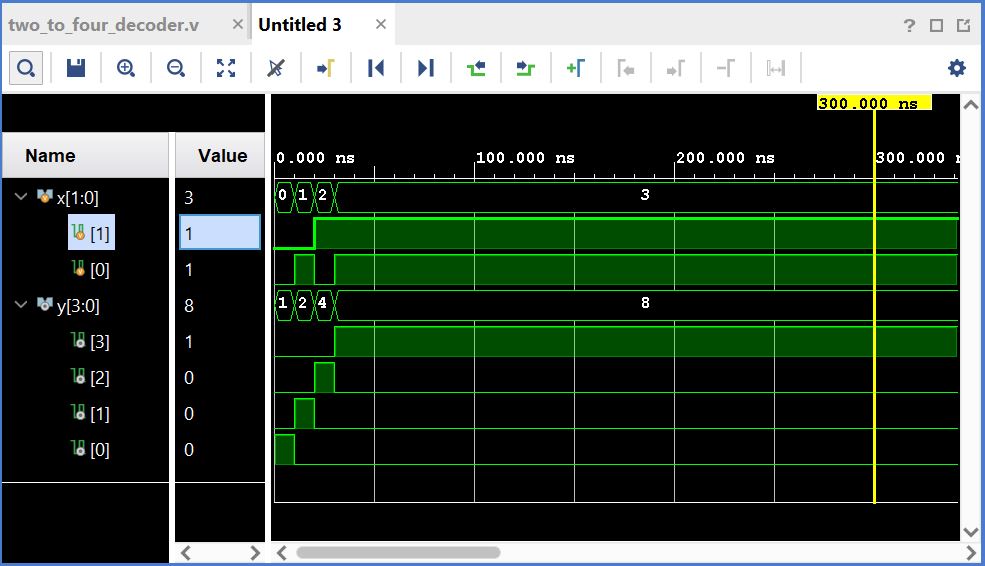
Figure 12. Decoder simulation shown using verilog and testbench.
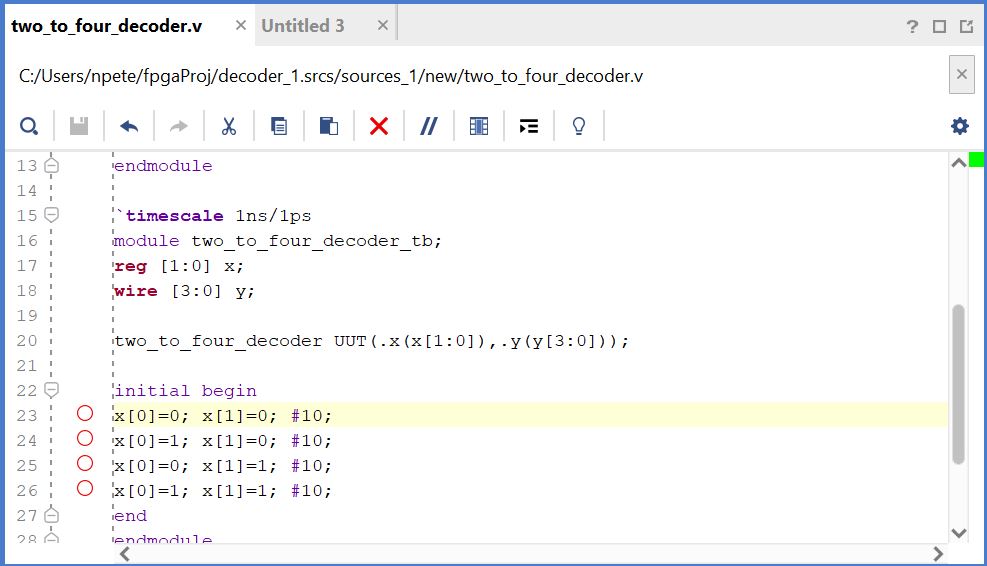
Figure 13. Test bench for the decoder expressing logic at certian times.
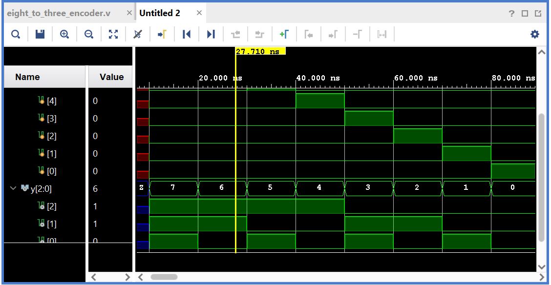
Figure 14. 8x3 prority encoder shown taking 8 various inputs and
simpifying to 3 outputs.
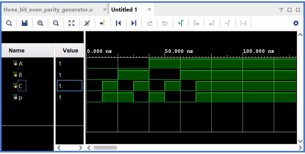
Figure 17. Even Parity generator and checker Simulation.
Figure 18. Even parity generator and checker using Basy 3.
Figure 19. Home alarm improvement and Car counter system improvement
using Basy 3.
5.
Discussion
All Applications are hands on which helps to reinforce logic. The
test benches are becoming easier as well as the wiring and code
implemetation. The Basy 3 and verilog are extremely useful and
practical. With more time, larger cuircuts can be produces and tested
with the basic knowledge becoming stronger.