Getting started with the W65C02SXB
Materials:
- W65C02SXB
- Micro-USB cable
- Breadboard
- Male to Female jumper wires
- LEDs
- SSDs (1 and 4 digit)
- Notepad ++ and the following downloads
First, download the following two items from WDC's getting started page here:

There are a couple more download links but they will not be needed for this tutorial. Create a WDC folder to store these in.
After
downloading WDCTools and the D2XX Driver, head over to this github link
and download the Xxcelr8r board projects. This will give us a template
in which we can program and debug the board with. The link is here.
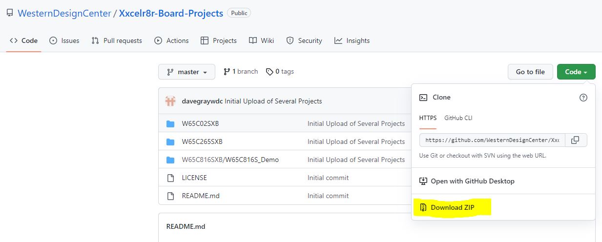
Extract the zip file into your WDC folder. These are all the materials we need to program with the W65C02SXB.
Now
lets turn an LED on. Plug the W65C02SXB into your computer via micro
USB. The ports on the board are now outputting basic signals and we can
test this by plugging in an LED. There is no code needed. We will be
utilizing the J3 ports located on the top of the board.
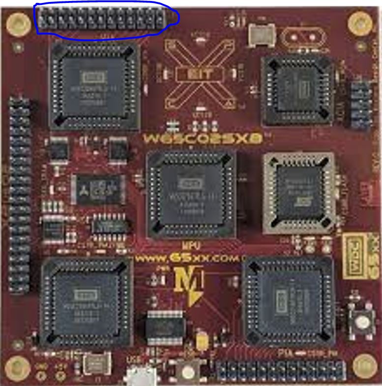
Pin
number one is denoted with a small dot above it. It is the top right
pin. The pin layout from the overhead view is as follows:
* | 25 | 23 | 21 | 19 | 17 | 15 | 13 | 11 | 9 | 7 | 5 | 3 | 1 |
| 26 | 24 | 22 | 20 | 18 | 16 | 14 | 12 | 10 | 8 | 6 | 4 | 2 |
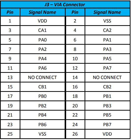
To
turn on an LED, wire pin 2 (Ground) to the cathode of an LED (shorter
lead/flat side) and any of the port pins (5-12 or 17-24) to the anode
(longer lead). The port pins have built in current limiting resistors
so you do not need to wire in an extra resistor. This is shown below:
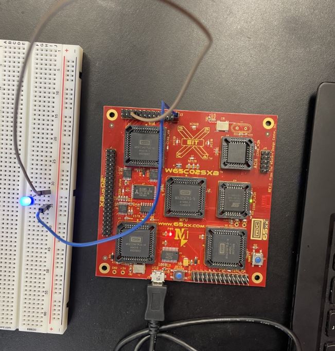
Now
that we know the board is on and outputting voltage, we can move onto
programming it. In the next tutorial, we will write a simple program to
blink this same LED.