CE 351 Report HW
8 Name:
Max
Krauss Email:
mtkrauss@fortlewis.edu
Intro: In this tutorial, we are using the esp32-Wroom to communicate
with an accelerometer and plot data in real time and in memory, using
an sd card.
Task
1:Repeat
the work above and show the results in a Video in your lab report.
Task
2:Repeat
the work above and show the results in a Video on your lab report.
Task
3:Read
the explanation in Code 1 - Code 5 above, repeat the work in Code 5,
show the demonstration video in your report.
Task
5:Modify the code to
receive all AccX, AccY, and AccZ data in separate data files
'AccX.txt', 'AccY.txt', and 'AccZ.txt'. Use Python to read these three
files and plot them in one figure (use Python is mandatory for CE
students). If you don't know Python, use MATLAB to plot them.(Refer
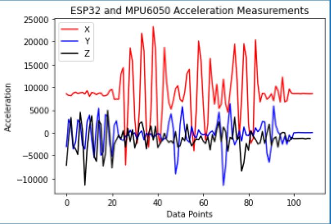
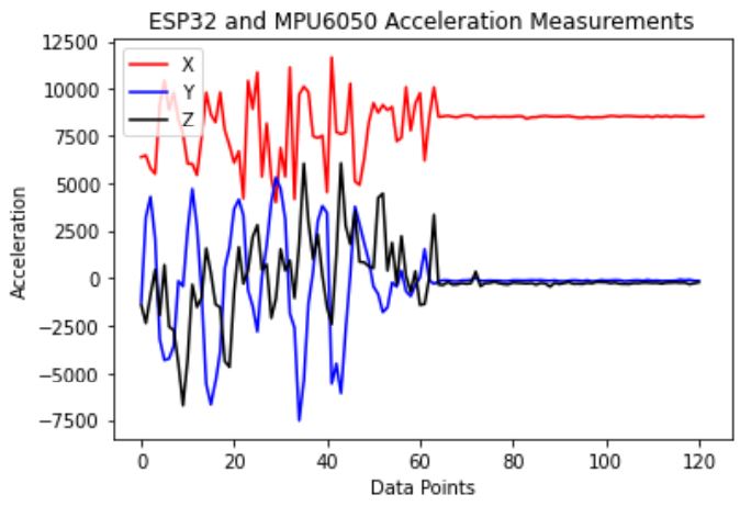
to the Appendix of this tutorial for an example Python code). Figure 5.1: Code changes for task 5 implementation.
Figure 5.1: Plotted data for task 5. Task
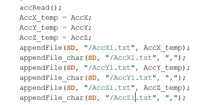
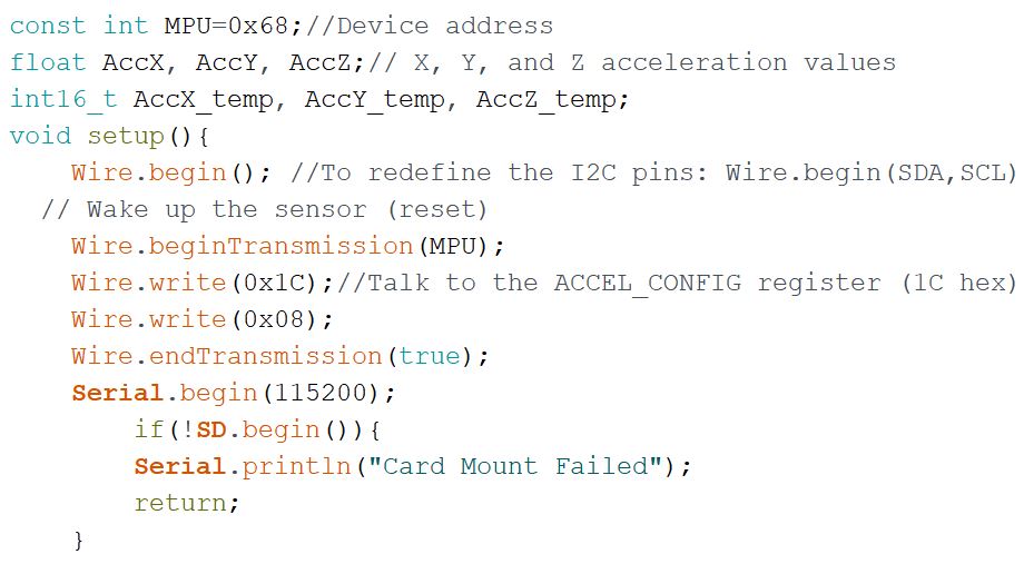
6:Change the data type
of AccX, AccY, and AccZ to 'float' and use intermediate int16_t
variables AccX_temp, AccY_temp, and AccZ_temp to store the 16-bit
accelleration data from the MPU sensor. TheAccX, AccY, and AccZ data
should be in the +- 4g range and being stored in the SD card in three
separate files. (similar to the technique used in Code 5 in Section 2
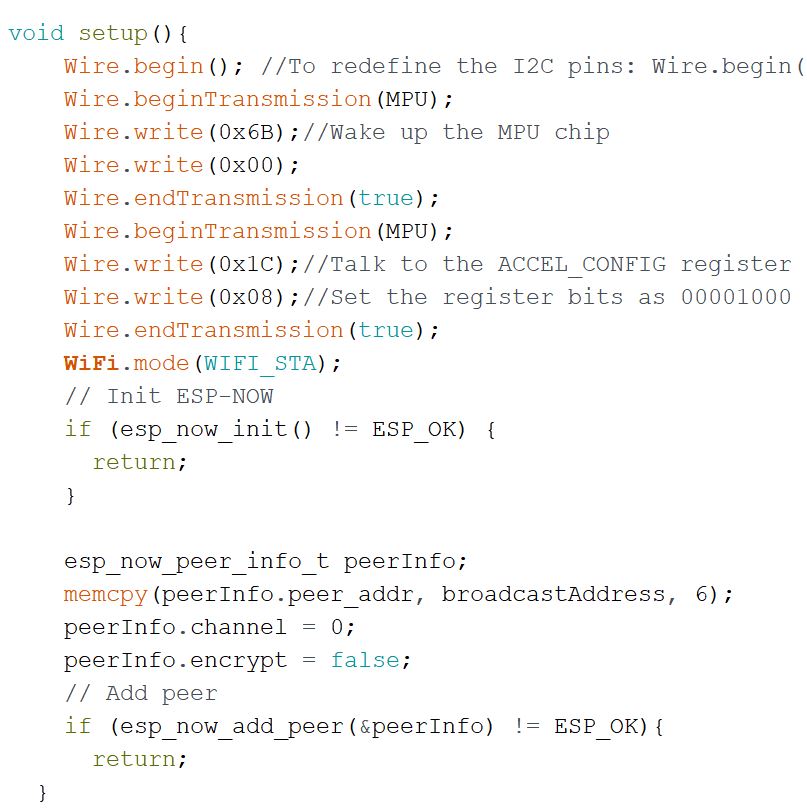
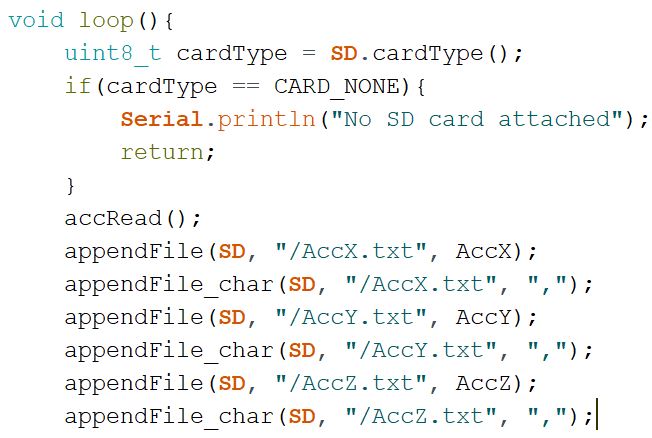
of this tutorial). \ Figure 6.1: Code changes for task 6.
Figure 6.2: Code changes for task 6 cont.
Task
7: Demonstrate
the results in a video in your report.
Task
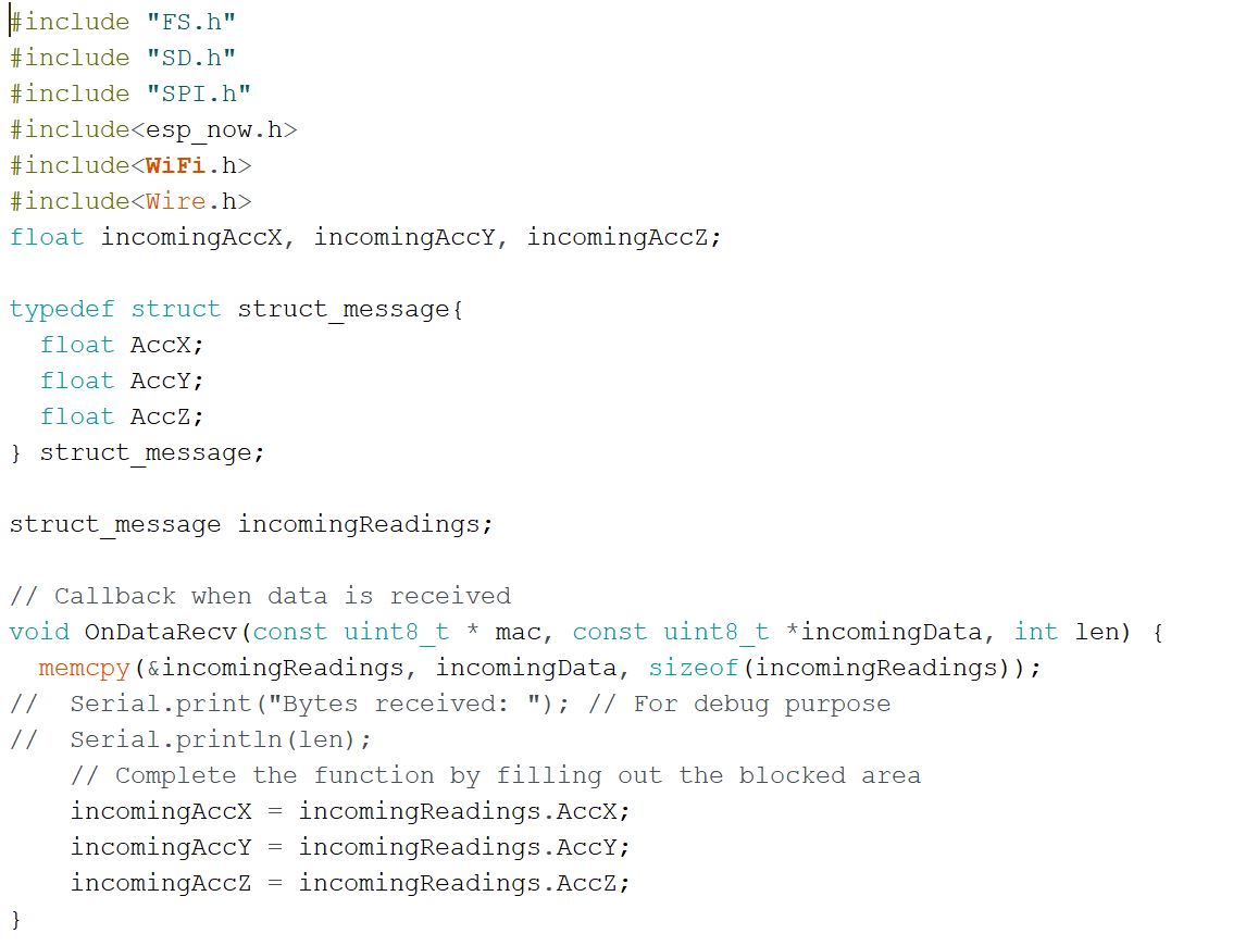
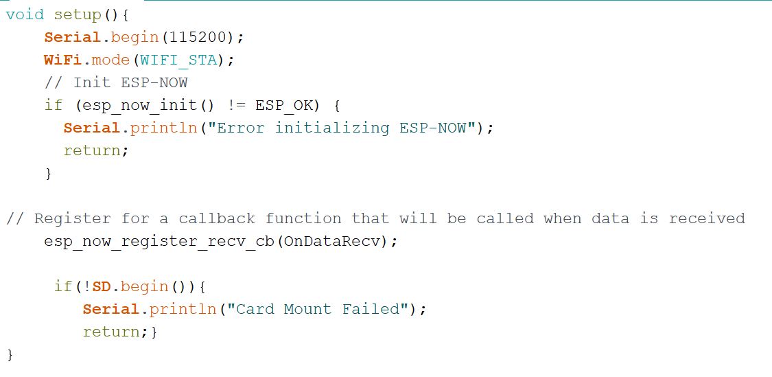
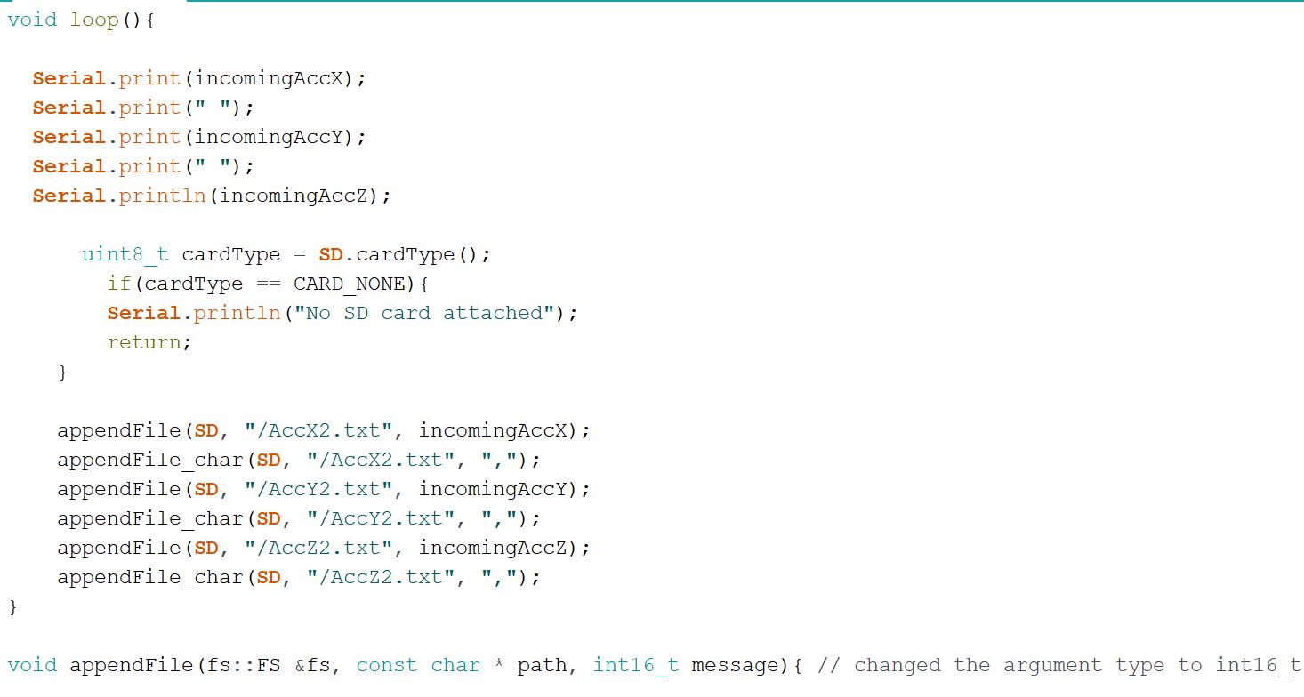
8:Design
the script to receive the accelleration data from the master wirelessly
by the slave and store the data to the SD card connected to the slave
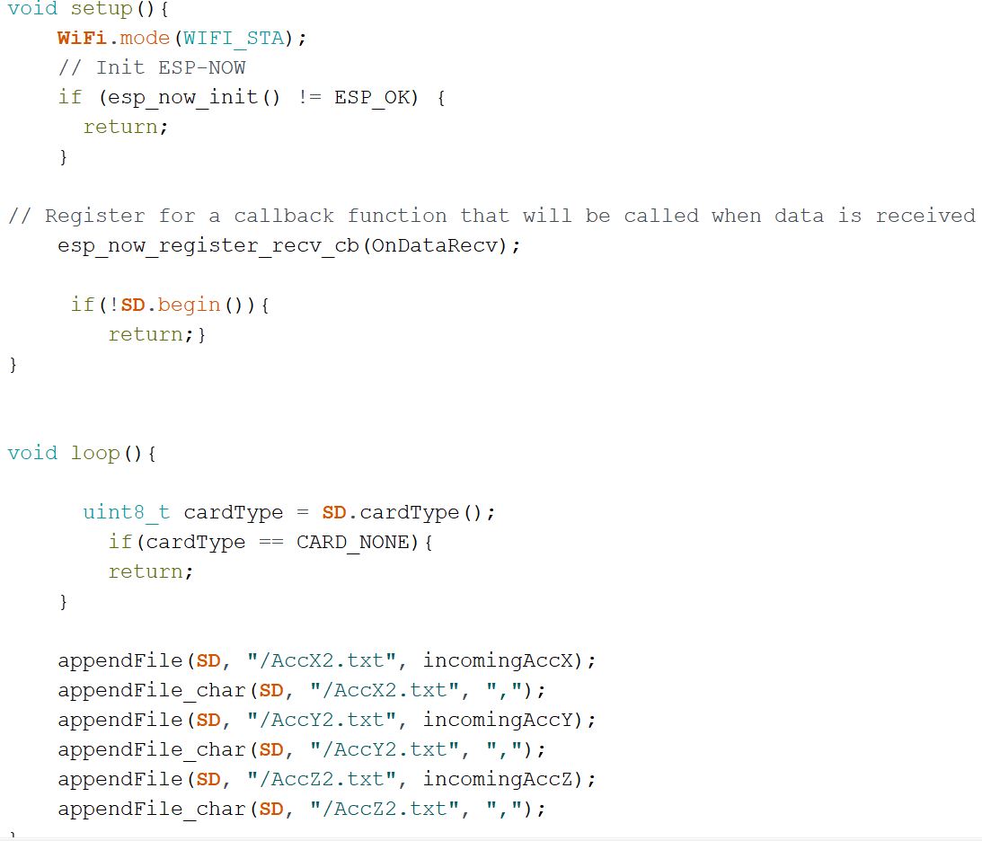
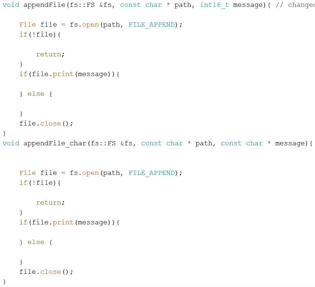
board. Figure 8: Code changes for task 8. The modules appendFile and appendFile_char were also added to the file.
Task
9:Remove
the division operation being performed on the ESP board, delete all the
unnecessary code for 'debugging purpose', remove the serial port
settings, and get a clean script for the master and the slave
respectively. Plot the saved data in Python (mandatory for CE students)
or MATLAB. The Python example is provided in the Appendix.
Figure 9.1: Removed division operation from ESP32 master.
Figure 9.2: Slave code with serial settings removed, cleaning up the script.
Figure 9.3: Data read from master and plotted in python.
Results:
After lots of trial and error, I was able to get the two ESP32 modules
to communicate successfully. I was then able to remove the serial
settings which cleaned up the script. This allows the reading data and
writing to the SD card to be done faster without interruption, which is
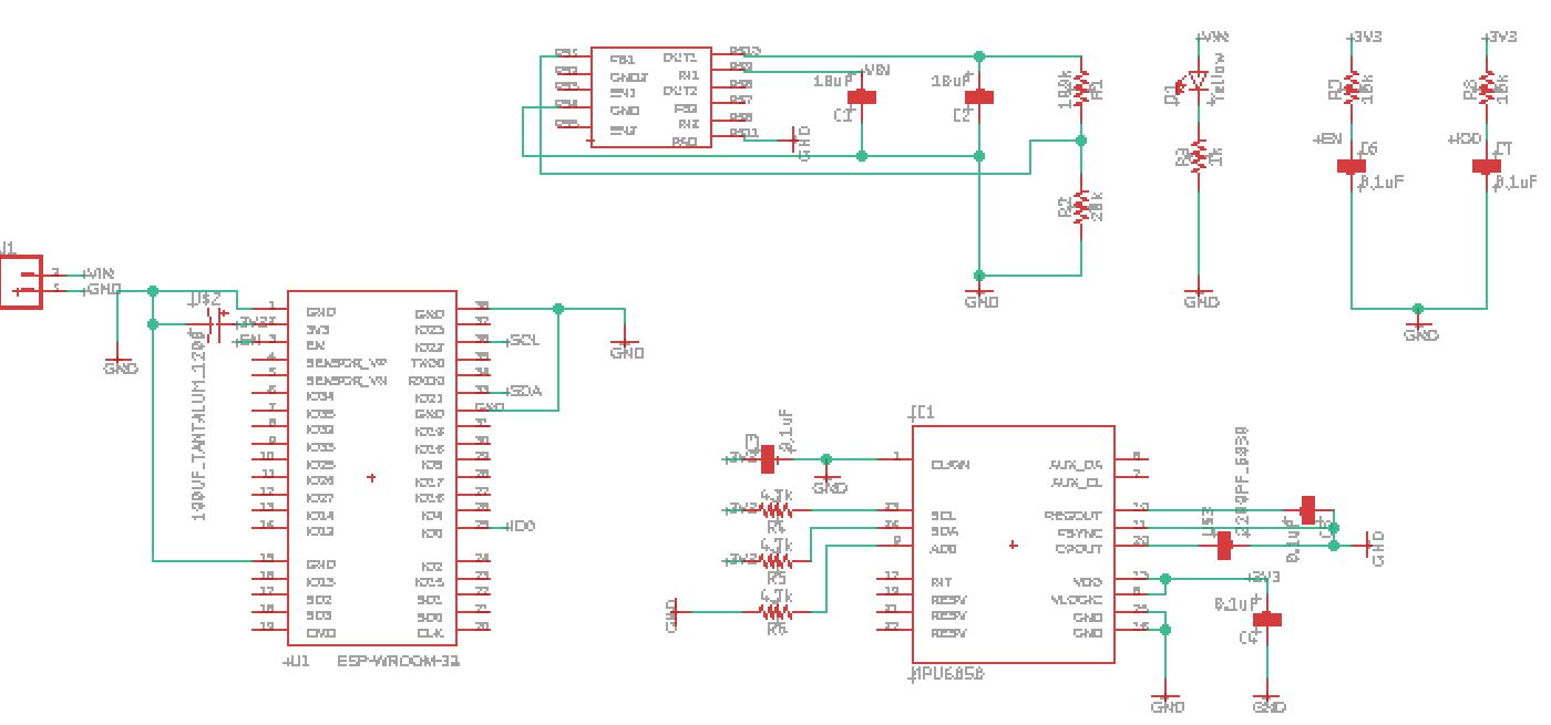
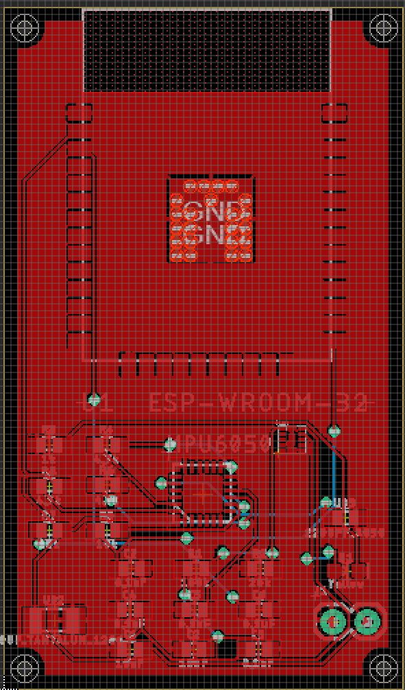
best for the application. Given below are the eagle PCB schematic and board layout that goes along with this project.
 \
\