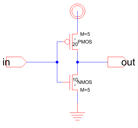
Running the simulations to ensure that it inverts
the input. From the building of the inverter under different input values/functions.
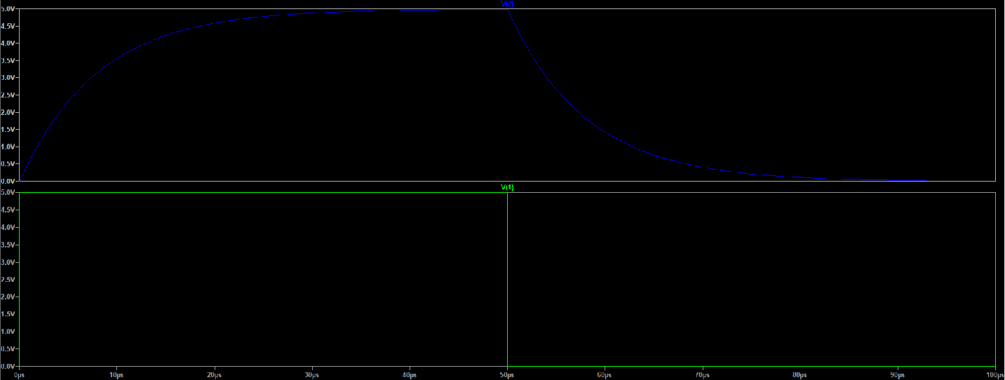
Constant input
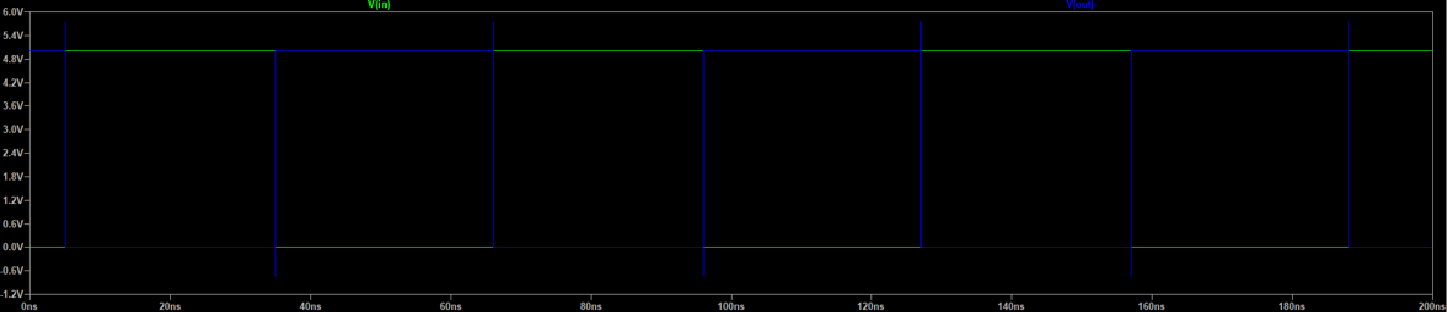
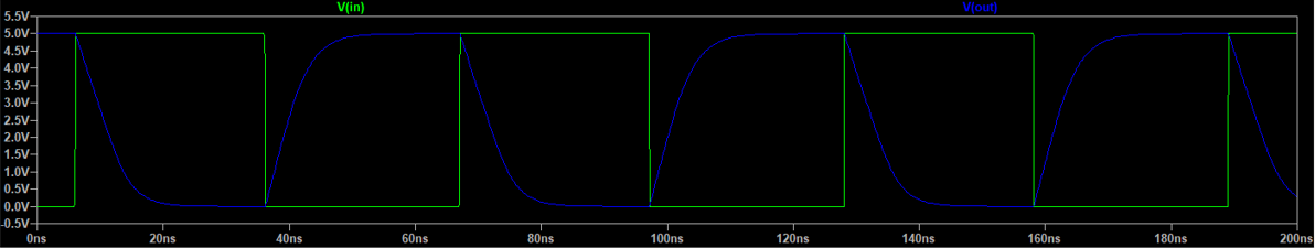
Pulse input
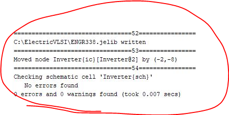
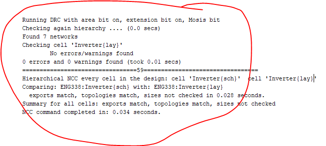
Ran a DRC and LVS check before I moved forward.
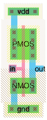
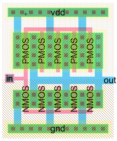
Built this layout of the inverter by following the tutorial given in the lab.
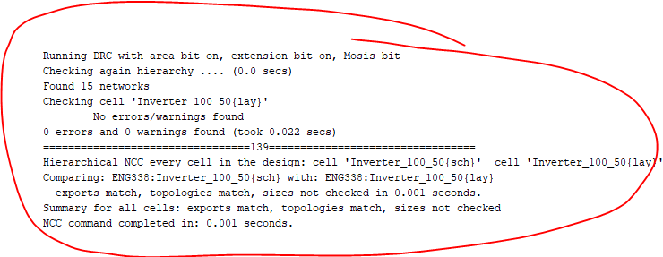
Building a larger inverter using the multiplier.
Verify the build DRC and LVS check.
Running simulations of the two different inverters under different capcitor loads. First 3 simulations are directed with 100 fF, 1 pF, and 10 pF caps
respectively.
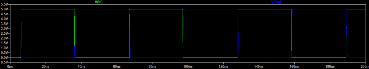
100fF

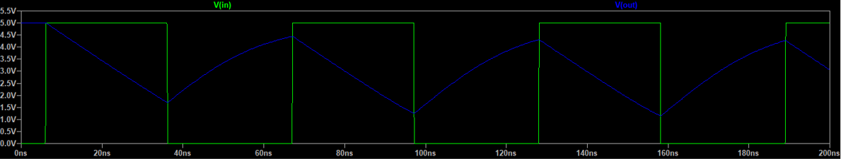
1pF
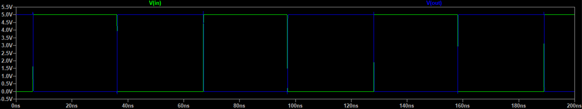
10pF
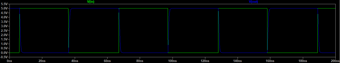
Using the same capacitor loads but with the larger inverter.
100fF
1pF
10pF