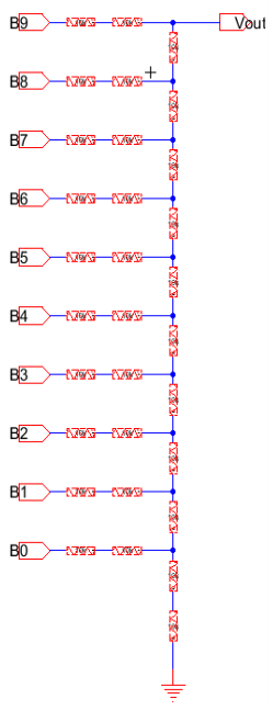
Starting with the reason that we prefer using this structure as a subcell is that we can create a layout of the subcell and copy/paste it to form the R_2R ladder.
This is a very important trick in the VLSI design.
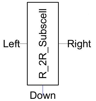
After the subcell is done, I performed DRC/LVS check to ensure that the subcell is working. Then created an icon from it.
On to creating a new schematic view, call it 'R_2R_Ladder' to differentiate it from the one in Lab 2. Copying and paste 10 of this in this view. To create a icone for this ladder.
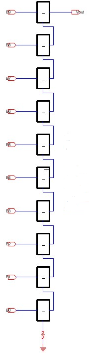
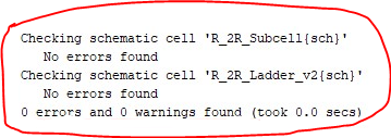
Run DRC: To ensure that it is DRC clean.
Task (2)
The ADC is ideal so we can't create a
layout of it. Let's just replace the DAC we created in Lab 2 in the
simulation and run it. Because this DAC has passed NCC (LVS) with the
layout view, if the schematic works, we can say the layout is correct
too. They have the same netlist and electrical connections which were
verified by NCC (LVS).
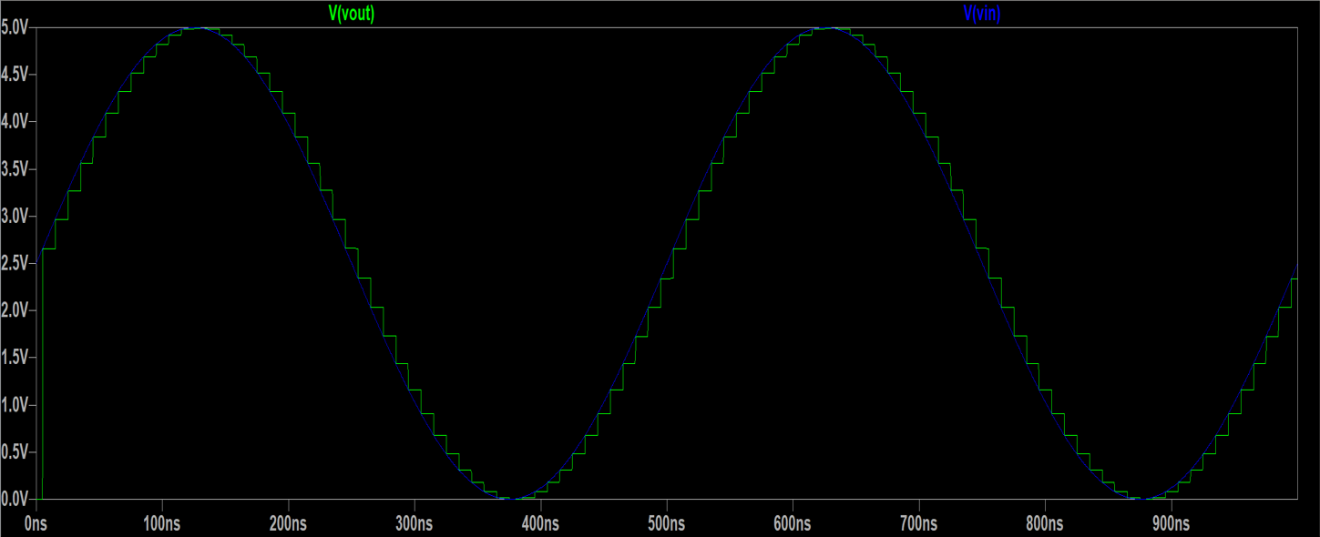
Next the R-2R Ladder DAC icon was used in a copy of the simulation used in the R-2R Ladder DRC connected to the ideal subcells.
Next the R-2R Ladder DAC icon was used in a copy of the simulation used in the R-2R Ladder DRC connected to the ideal subcells.
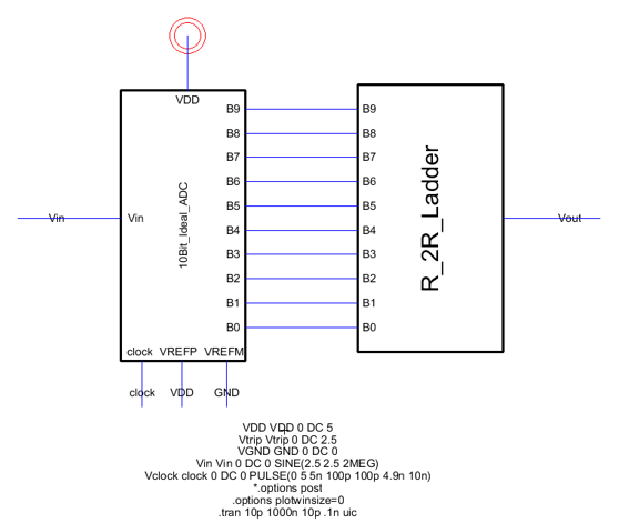
Simulation results in LTSpice of replacing the DAC with the 'R_2R_Ladder'.