CE338 Lab 2023 Fall
Lab 1 Superposition, Thevenin's Equivalent Circuit, LTSpice
Name: Jesse Moder
Email:
jmmoder@fortlewis.edu
1. Superposition, Thevenin's Equivalent Circuit, and LTSpice
2. Introduction
Superposition theory is useful for analyzing a circuit that has
multiple
voltage sources. This method allows for the voltages and currents
across the resistors of the circuit to be calculated by focusing on one
voltage source at a time and treating the other sources as a wire. By
summing the respective voltages and currents across each resistor from
each voltage source, the total voltage and current across each resistor
can be calculated.
Thevenin’s equivalent circuit is useful for determining the equivalent
resistance of a circuit and the equivalent circuit voltage. The
resulting simple circuit helps increase efficiency when exploring how
changing the load resistance effects the circuit. This method helps to
design circuits for specific specifications and applications.
3. Materials and Methods
Circuit 1:
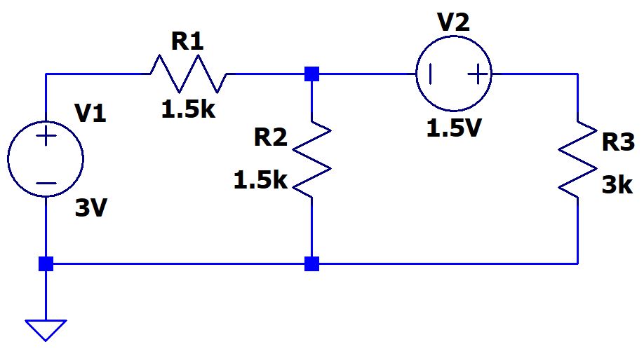
Figure 1: Circuit diagram for superposition analysis.
Curcuit 2:
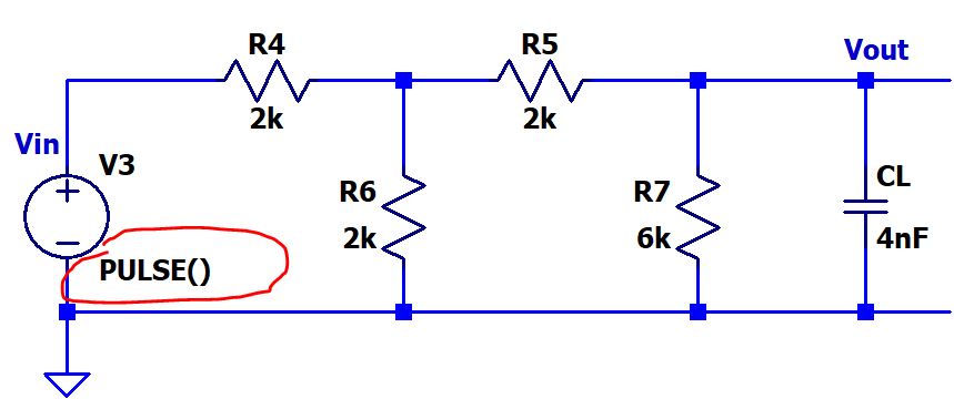
Figure 2: Circuit diagram for Thevenin's equivalent analysis.
By hand, the currents
and voltages across the resistors of circuit 1 were analyzed using
superposition. The Thevenin’s equivalent resistance and voltage were
determined for circuit 2. LTSpice was used to analyze the two circuits
using software, as well as to confirm the hand calculations were correct.
4. Results
Circuit 1:
The circuit was first analyzed using superposition, as shown in Figure 3.
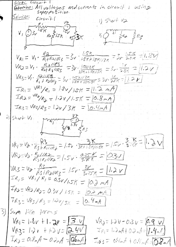
Figure 3: Hand calculations for the voltage and the currents of circuit 1 using superposition.
Table 1: Calculated values for the voltage and the currents of circuit 1 using superposition.
VR1
(V)
|
VR2
(V)
|
VR3
(V)
|
IR1
(mA)
|
IR2
(mA)
|
IR3
(mA)
|
3
|
0.9
|
2.4
|
1.4
|
0.6
|
0.8
|
The voltages were then
simulated using LTSpice. Figure 4 shows the simulated voltages, and
Figure 5 shows the simulated currents.
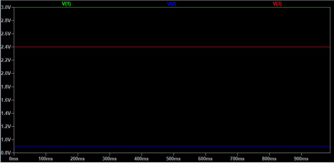
Figure 4: The LTSpice simulation of the voltages across the resistors of circuit 1.
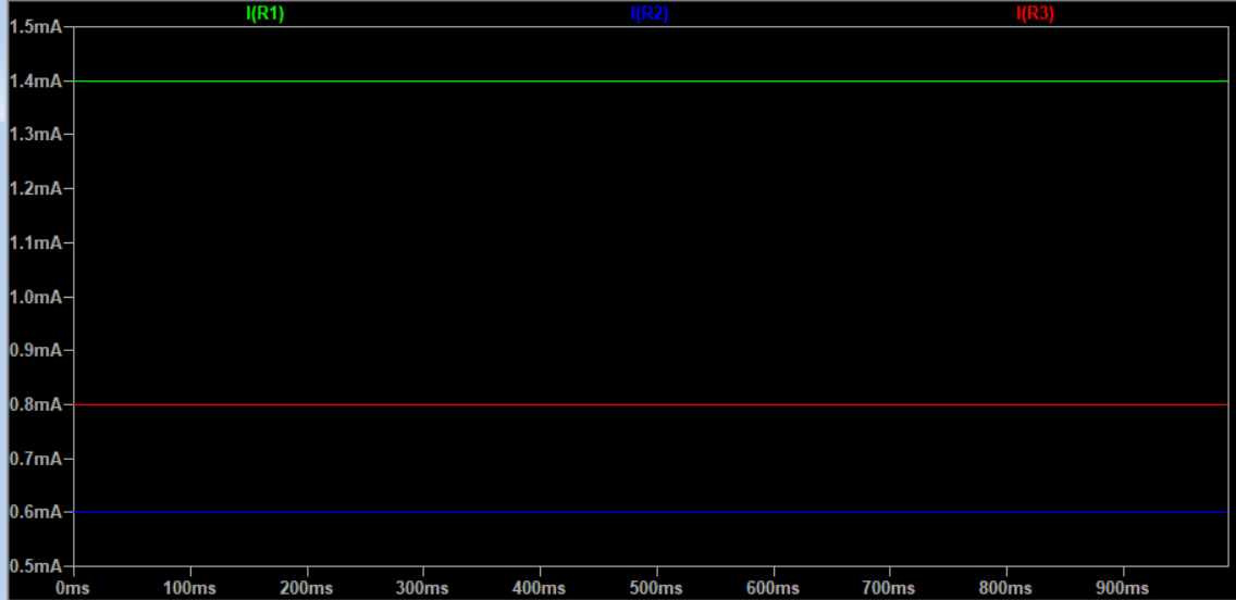
Figure 5: The LTSpice simulation of thecurrents across the resistors of circuit 1.
Figure 6 shows the code for the LTSpice simulations.
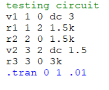
Figure 6: The LTSpice code used for simulation of the circuit.
Circuit 2:
Figure 7 shows the hand calculations for Thevenin's equivalent resistance and voltage of circuit 2.
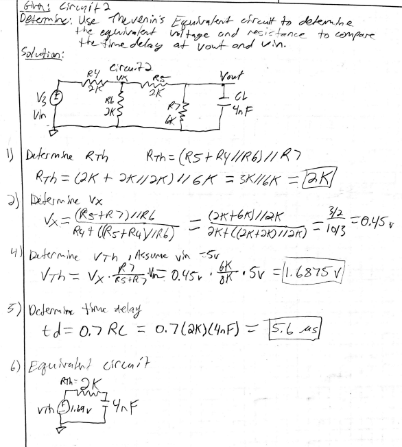
Figure 7: Hand calculations for Thevenin’s equivalent voltage and resistance of circuit 2.
The Thevenin's equivalent resistance was 2 kohm and the equivalent voltage was 1.6875 V.
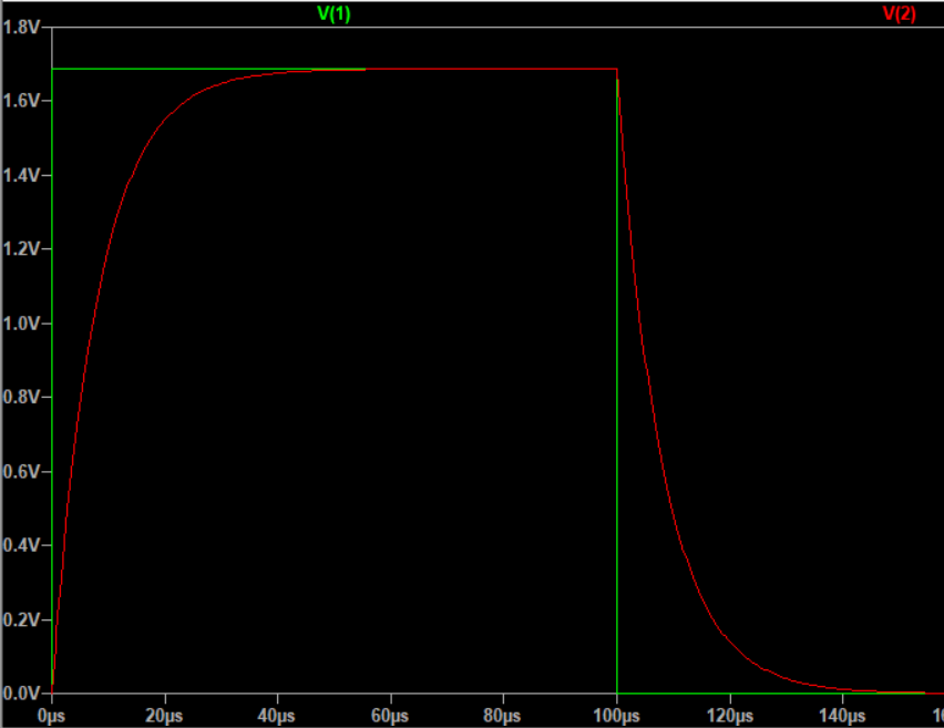
Figure 8: Thevenin's equivalent voltage and time delay of the circuit.
The time delay was
observed at 0.84375 V, which was half of the maximum circuit voltage,
1.6875 V. The time delay according to LTSpice was 5.59 microseconds,
while the hand calculations produced a time delay of 5.6 microseconds.
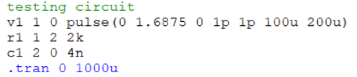
Figure 9: LTSpice code for simulation of circuit 2.
5. Discussion
The small difference in time delay from the hand calculations and LTSpice was
likely due to manually placing the cursor on the line and reading the value
where half the maximum voltage and Vout intersect.
The LTSpice simulation voltages and currents for circuit 1 matched the
hand calculations performed using superposition. Learning how to
simulate in LTSpice using code instead of creating a circuit diagram
was beneficial because it could save time in the future, and the code
is compact and neat.
LTSpice is an incredibly useful tool for analyzing circuits. These
examples are basic but demonstrate how much time can be saved using
software to analyze circuits. Along with increasing efficiency, LTSpice
also increases confidence in the analysis because it is so widely used
and trusted. Performing the hand calculations helps to gain an
appreciation for how powerful these circuit design software tools are.