CE 432 Practical Robot Design 2023 Fall
HW 9 Balancing Robot
Name: Connor O'Keefe
Email: cwokeefe@fortlewis.edu
Name: Jesse Moder
Email: jmmoder@fortlewis.edu
1. Title
Balancing Robot
2. Introduction
The objective of this assignment was to construct and program a two-wheeled balancing robot, as well as design a PCB for control of the robot.
3. Materials and Methods
The frame of the balancing robot was constructed with parallel acrylic boards and threaded rods to hold the acrylic boards together. Two NEMA17 stepper motors were installed at the base of the frame. Each stepper motor was connected to an A4998 stepper motor driver. A 6050 MPU was used to gather gyroscope and acceleration data. An Arduino Nano microcontroller was used to control the robot functionality. An encoder was used to tune the robot PID parameters. A joystick and two NRF24 wireless modules were planned for implementation of robot direction control. The code for the robot control can be found here.
4. Results
The following video shows the balancing function of the robot.
Video 1: Robot balancing demonstration.

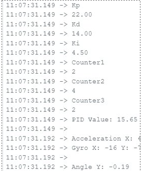
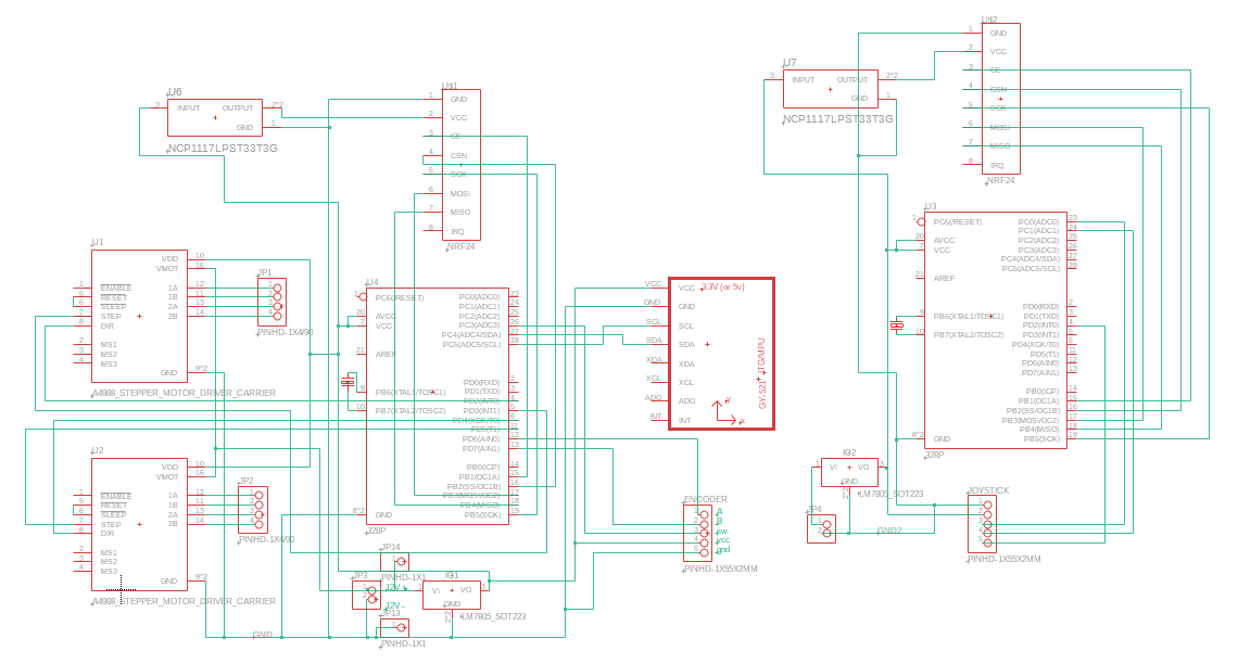
Figure 4 shows the schematic for the robot PCB.
Figure 4: PCB Schematic.
.
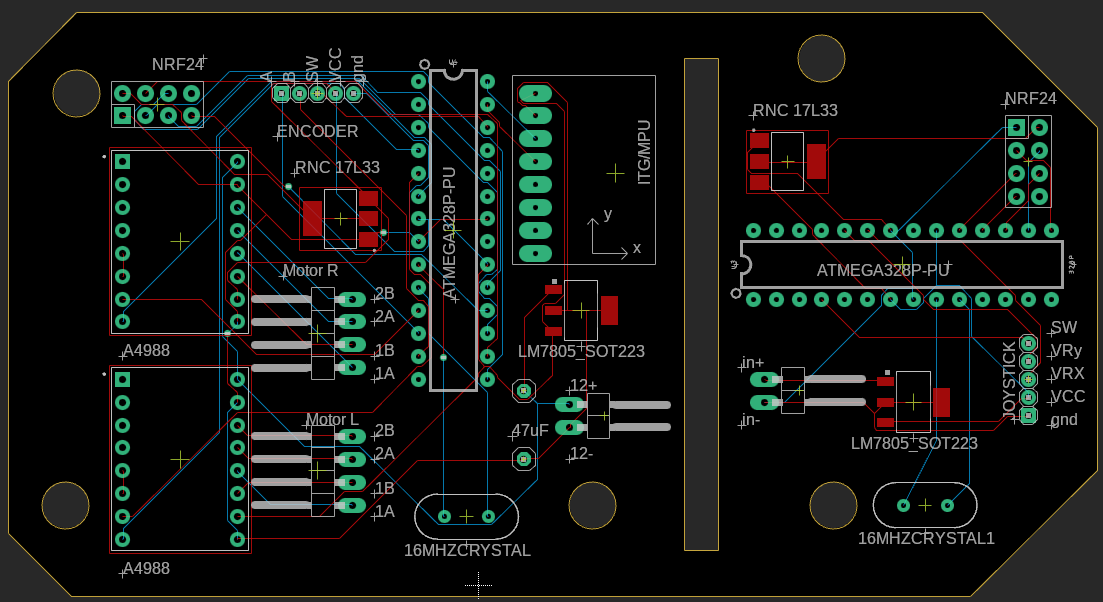
Figure 5 shows the PCB layout. The PCB will break into two halves, one for control of the robot and one for the joystick and wireless module.
Figure 5: PCB board layout
5. Discussion
Originally, we had used a DOIT ESP32 DEVKIT V1 Board to program the robot because of its WIFI and Bluetooth functionality. We had difficulty with the encoder interrupt functions, as the encoder would only count in one direction when using an interrupt but would work as expected inside the loop function. We also had challenges with writing to the register ports. When we switched to the Arduino Nano microcontroller and uploaded the code from this tutorial (https://electronoobs.com/eng_arduino_tut159.php) and adjusted the acceleration offset, the balancing function worked as expected. One encoder was implemented to control the Kp values of the PID function. The Ki and Kd values were unchanged and did not affect the function of the robot.
Overall, this project was challenging and interesting, as it tested our troubleshooting and code implementation abilities. Creating a balancing robot was an effective way to bring together the skills we have learned this semester, from controlling a stepper motor with an encoder, using an ESP32 microcontroller, troubleshooting code, making proper wire connections, and adjusting parameters with an encoder.