Upon receiving the PCB, I broke the PCB into two parts along the planned cutouts. The connection
pads for the two halves were soldered together. The 8 headers for each side of the ESP32 Dev Module were
soldered and the ESP32 was installed. Three pins for the RX, TX, and GND connections were soldered and
a push button was used to connect the pads of gnd and IO16 for uploading code.
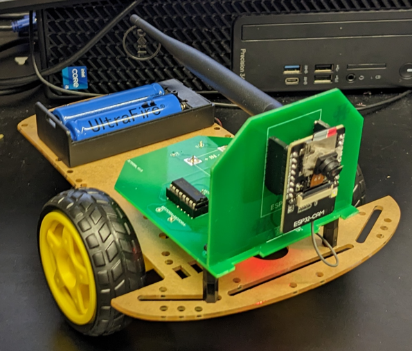
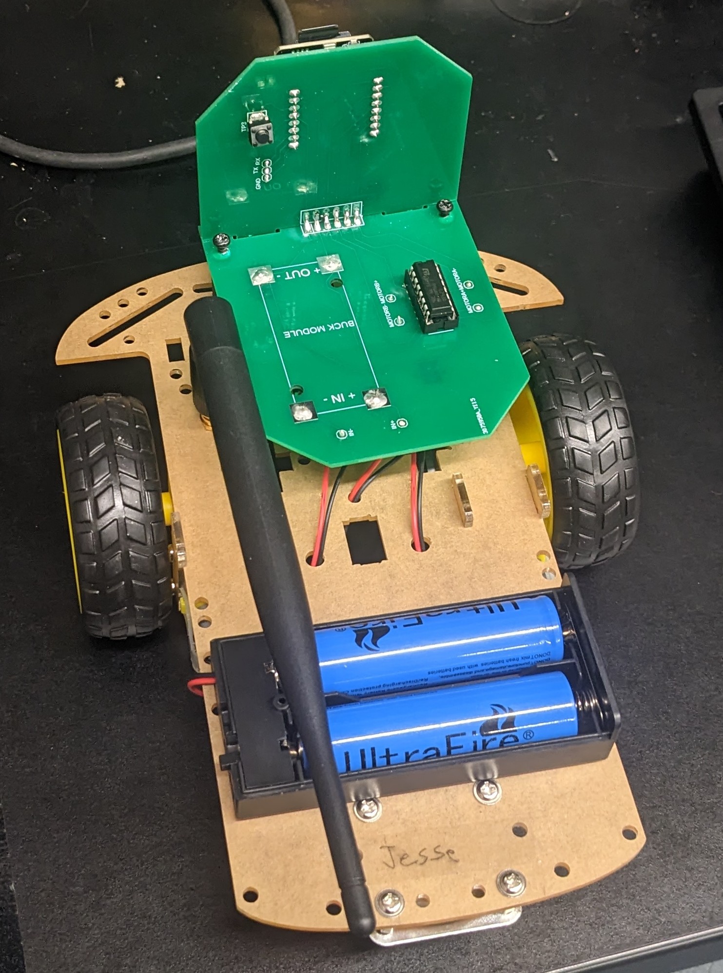
The motor driver and LM2596 voltage regulator were also soldered to the PCB. I accidentally mirrored
the LM2596 on the PCB design, so I connected it to the bottom of the PCB so the + and - terminals aligned
properly. There was plenty of room underneath the PCB with risers connected. The motor A and B + and -
wires were connected, as well as the + and - wires from the battery.
I uploaded the same code used for the prototype board robot car, and the robot behaved as expected.