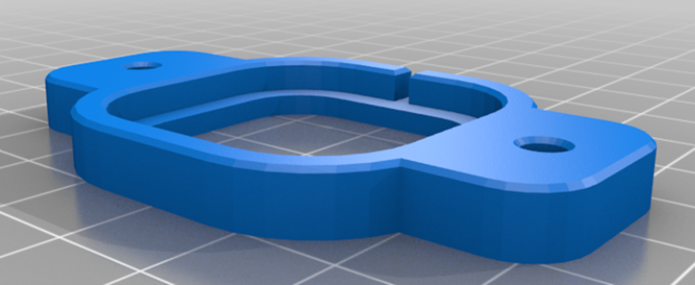
Print four load cell housings. The .stl file for the housing can be found here.
Install the load cells in the housing.
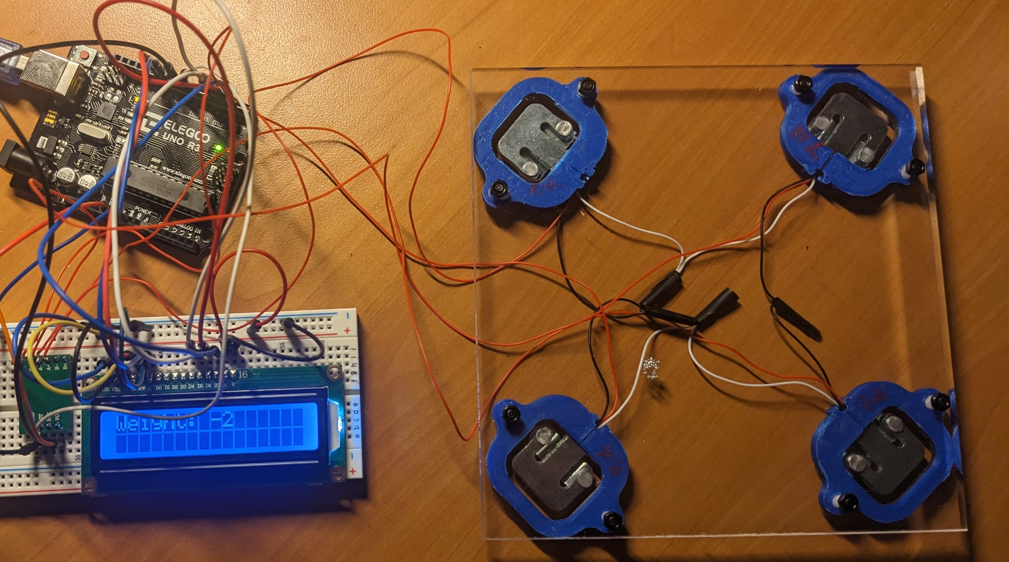
Drill holes and attach the load cells to the four corners of the acrylic board.
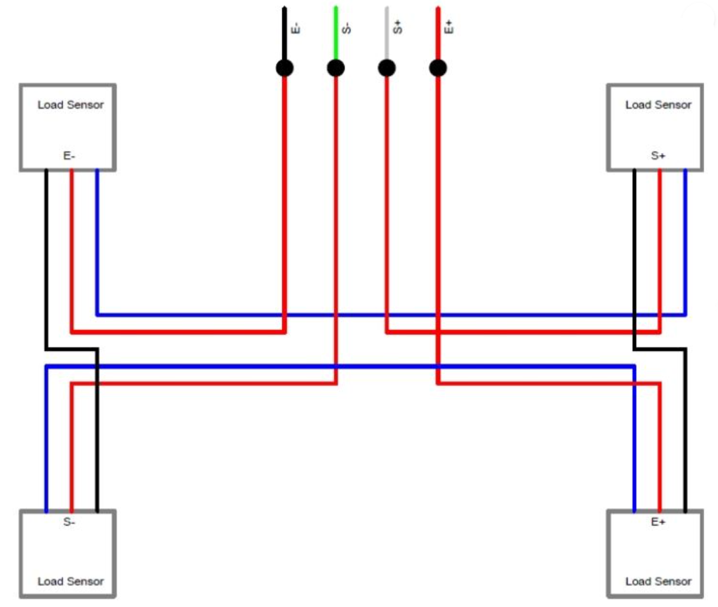
Connect the wires of the load cells, as shown in the following image,
and use heat shrink tubing to cover the soldered connections.
Trim the white and black wires to length as necessary. The white wire for the load cell is blue in this image.
\
Solder resistors, capacitors, crystal, ATMEGA32B, 8550 transistor, and pins to the PCB. Connect the four red wires from the load
cells to the correct E+, E-, S+, and S- locations on the PCB. Connect
the OLED display and power wires to the PCB. (image coming soon)
Connect the DT pin of the HX711 to A5 and the SCK pin to A4.
Upload the calibration code found here to the ATMega32B and find the calibration factor, then upload the second code
with the calibration factor updated.
The scale is now ready to weigh objects.
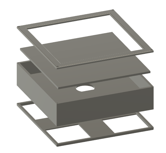
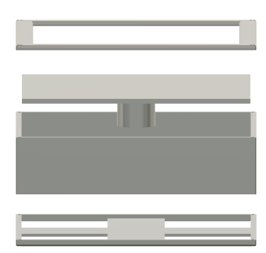
3d print the scale housing components, found here. Insert the scale between the bottom layer with the 4 square cutouts
and the body of the scale. Place the pcb in the layer between the body
(with the circular cutout) and the flat plate. Feed the scale wires
through the rectangular cutout of the body. Assemble the compoenents as shown and use 8 M2 screws (4 for the bottom and 4 for the top)
to secure the scale components.

 \
\