Figure 1 shows the sample and hold circuit and DRC.
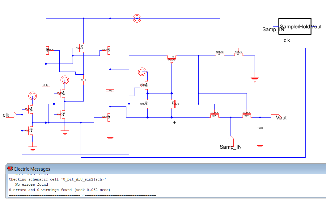
Figure 2 shows the simulation schematic for the sample and hold circuit.
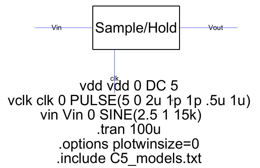
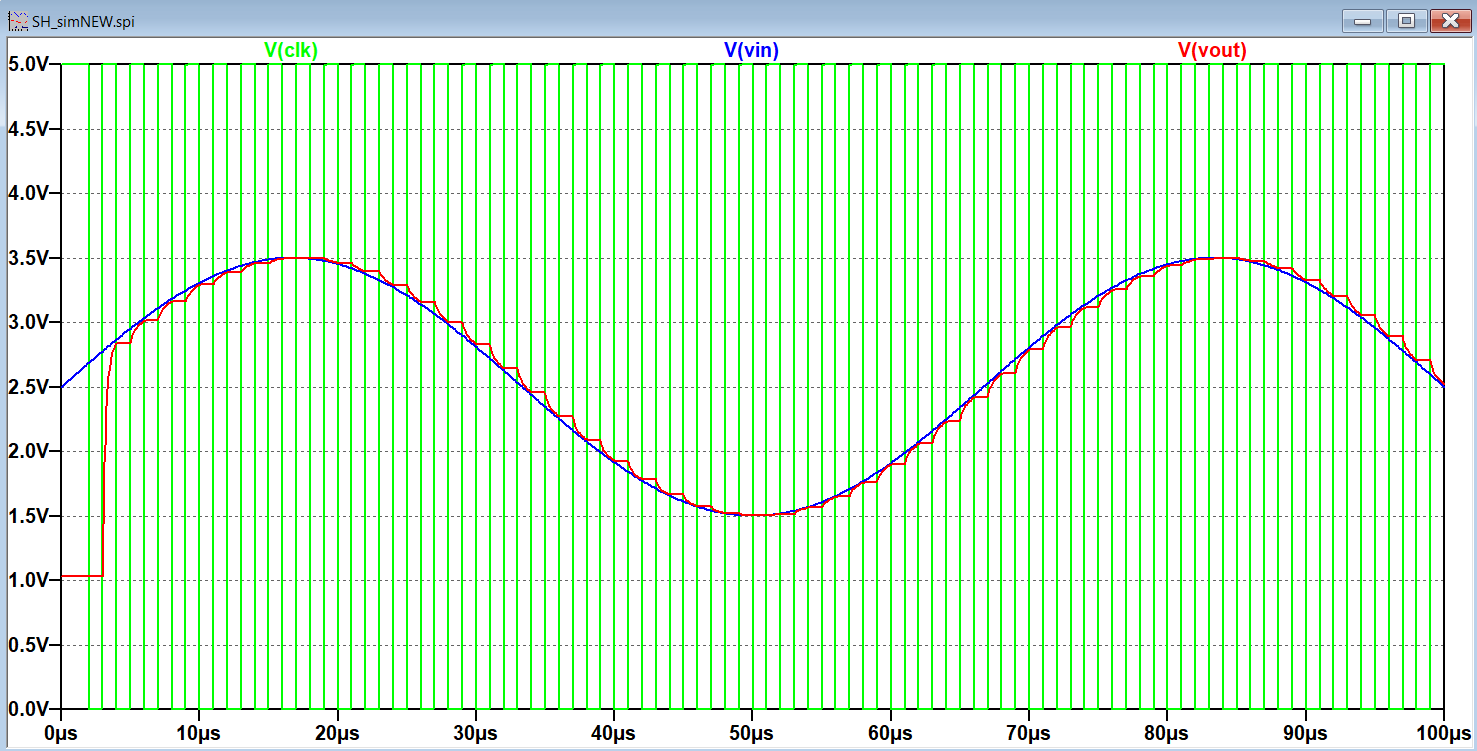
Figure 3 shows the LTSpice simulation for the sample and hold circuit.
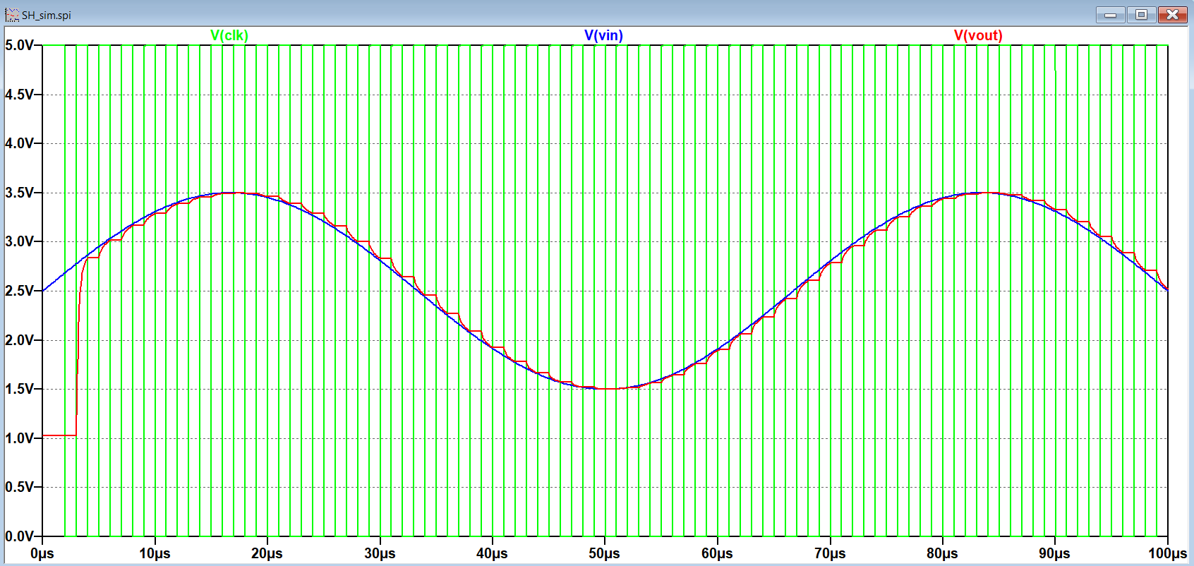
Figure 4 shows the simulation schematic for the sample and hold connected to the comparator.
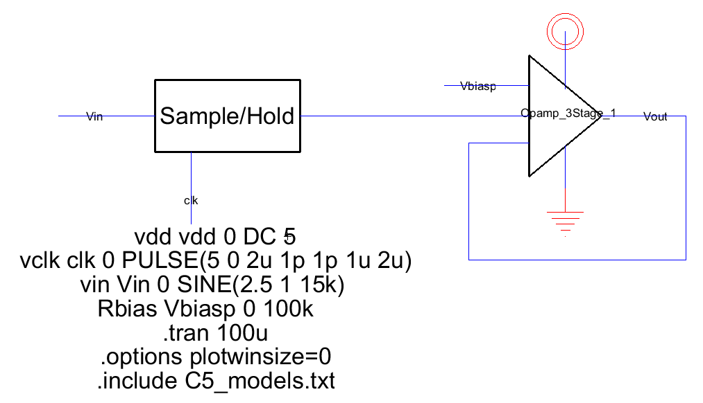
Figure 5 shows the LTSpice simulation for the sample and hold connected to the comparator.
5. Discussion
With a fast clock cycle, the voltage out closely follows the voltage in with a small deviation during the clock cycle where the voltage is held. The simulations for just the sample and hold circuit and
the sample and hold circuit with the comparator were nearly identical in tracking Vin, although the sample and hold with comparator appeared to follow Vin more closely than just the sample and hold circuit.
With just the sample and hold circuit, the signal was sampled at the falling edge and held during the clock cycle. When the comparator was connected, the signal was sampled at the rising edge and held between
clock cycles. It will be interesting to see how closely Vout follows Vin when the full circuit is constructed and simulated.