Lab 5 The Inverter
Jesse Duran
Spring 2021
ENGR 338
Introduction:
Throughout the course of this lab we will create a schematic of both a
20/10 and 100/50 inverter. We addionally layed out NMOS and PMOS
transistors. This builds on the skills we have been developing over the
last couple labs
Task 1:
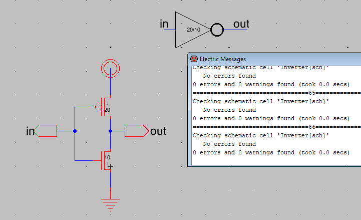
Figure 1. 20/10 Inverter schematic. DRC clean
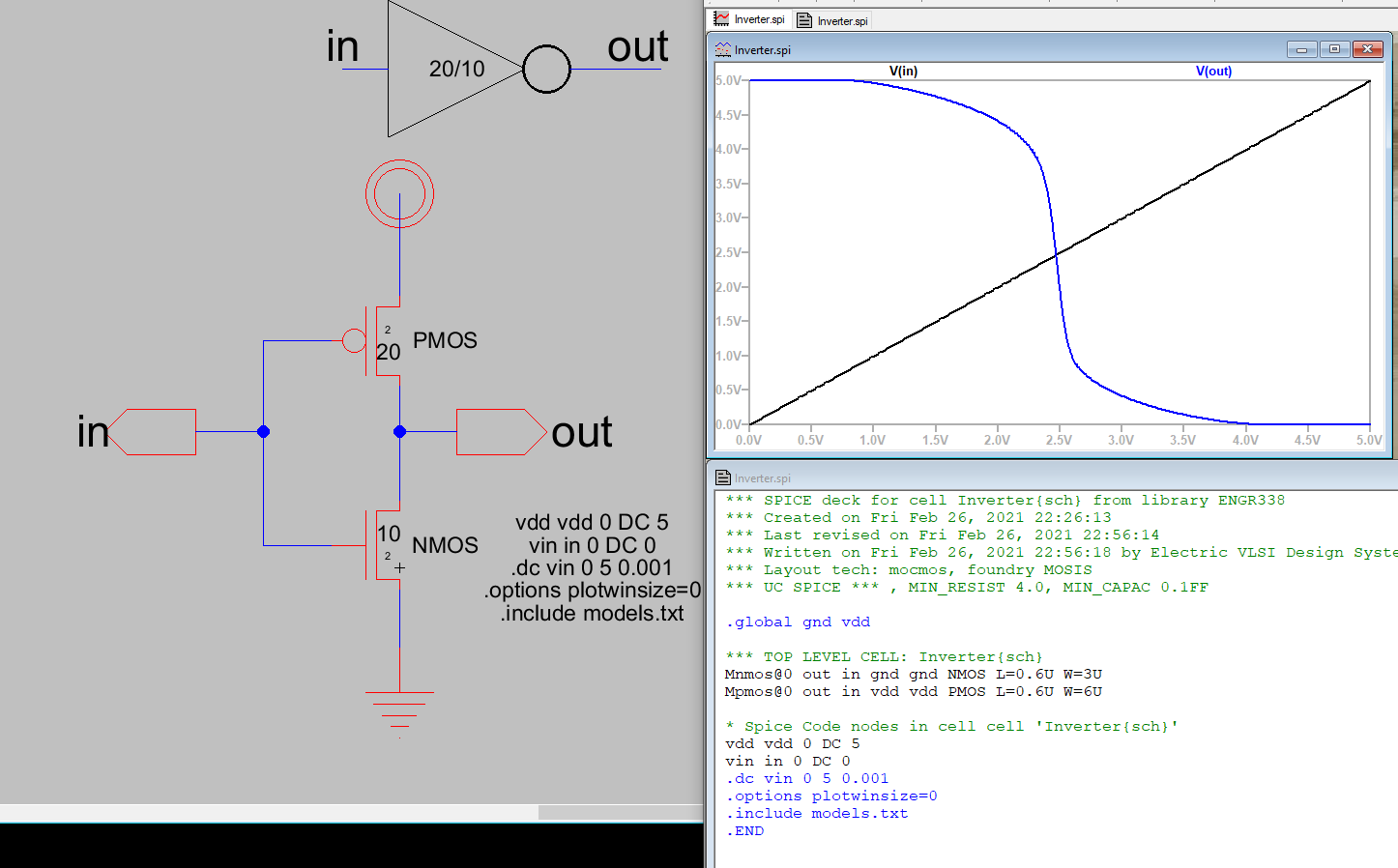
Figure 2. LTSpice simulation of 20/10 inverter using DC analysis
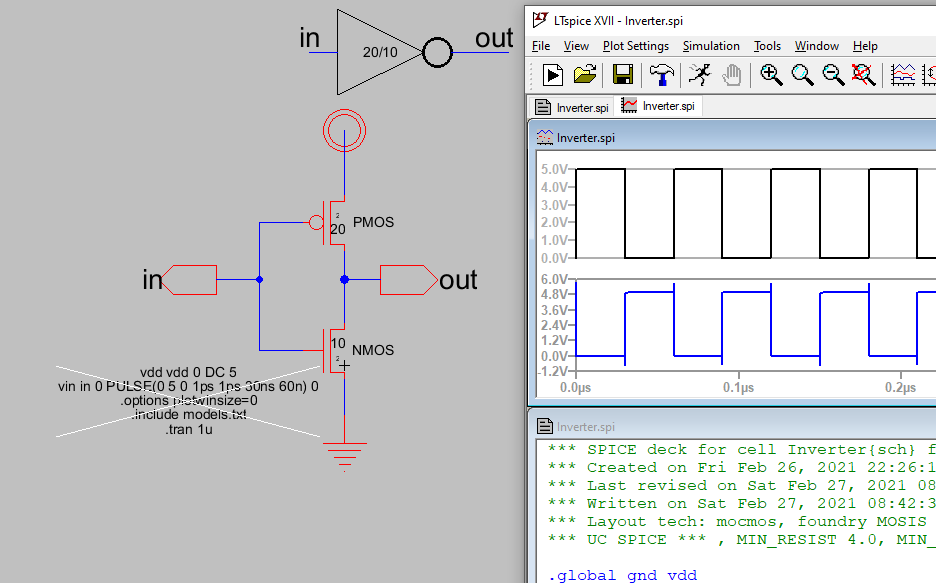
Figure 3. LTSpice simulation of 20/10 inverter using transant analysis
and Pulse function as input
Task 2
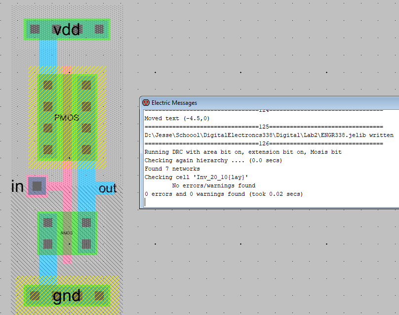
Figure 4. 20/10 Inverter layout. DRC clean
Task 3
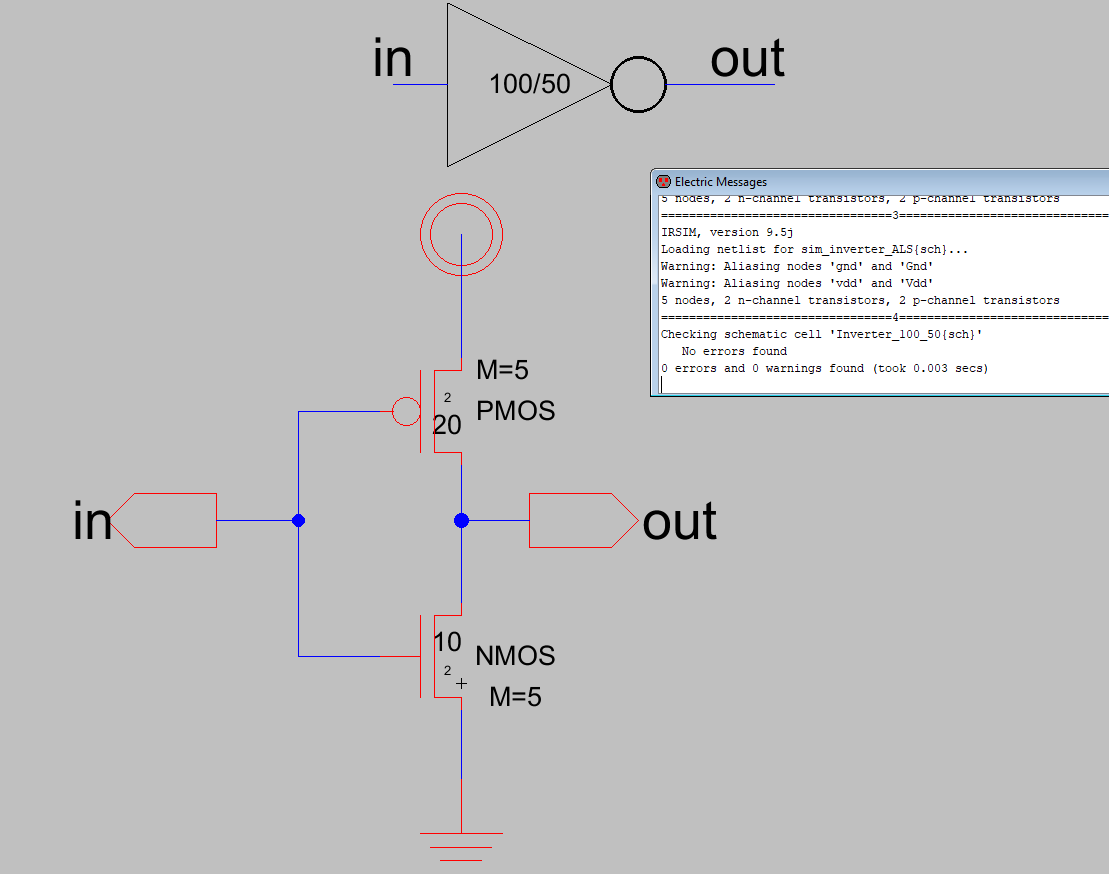
Figure 5. 100/50 inverter schematic single MOS symbols to represent 5
in parallel. DRC clean
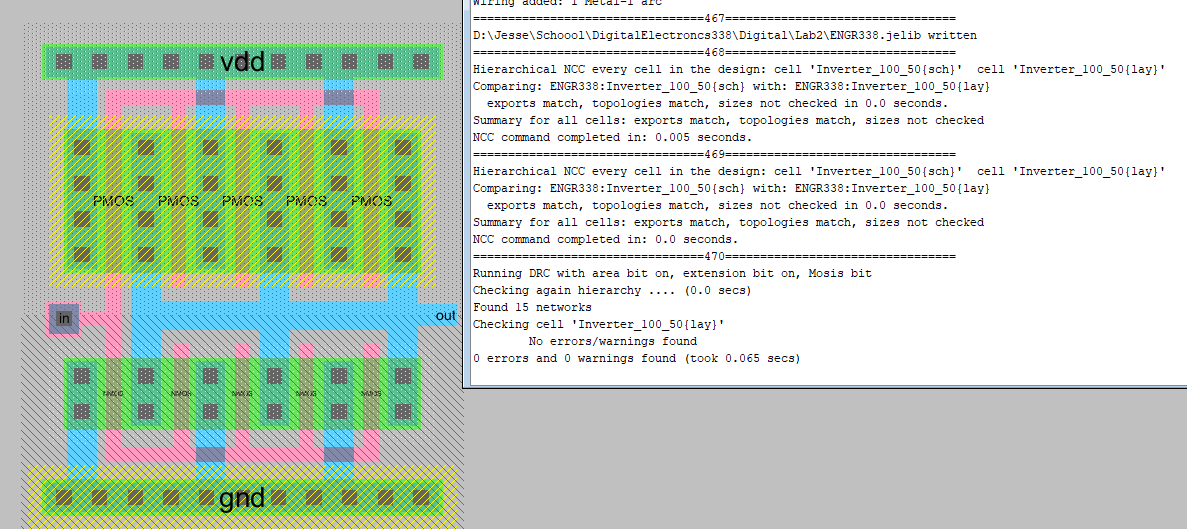
Figure 6. 100/50 Inverter layout. Gates of NMOS and PMOS are shorted
together. DCC, NCC clean.
Task 4
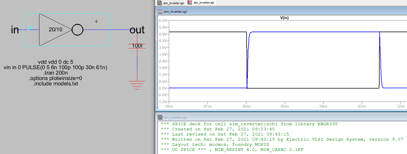
Figure 6. LTSpice simulation of 20/10 inverter powering up 100fF
capacitor.
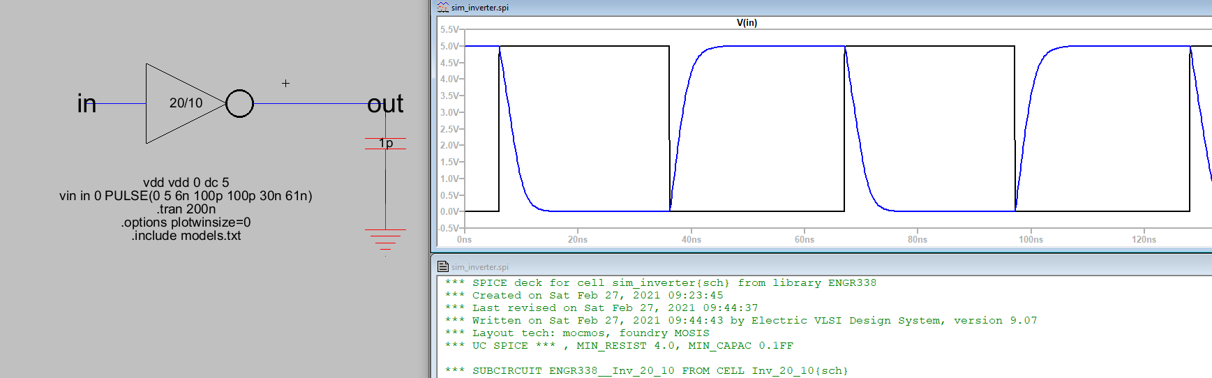
Figure 7. LTSpice simulation of 20/10 inverter driving 1pF capactior.
Time delay to full charge is larger than 100fF.
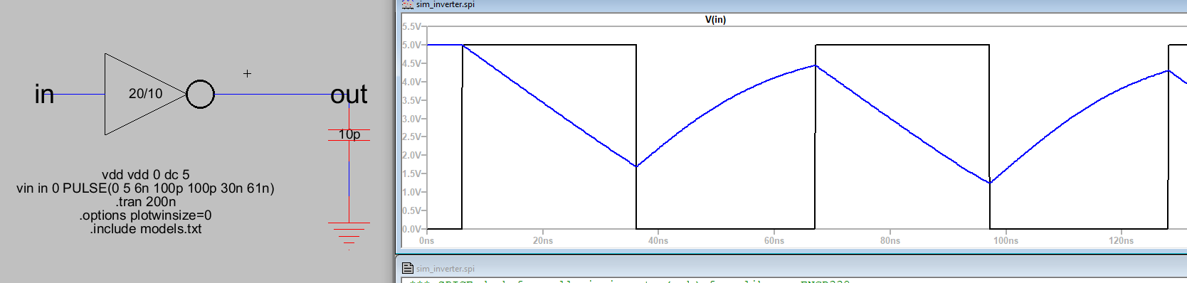
Figure 8. LTSpice simulation of 20/10 inverter. Circuit struggling to
drive 10pF cap, its is too large.
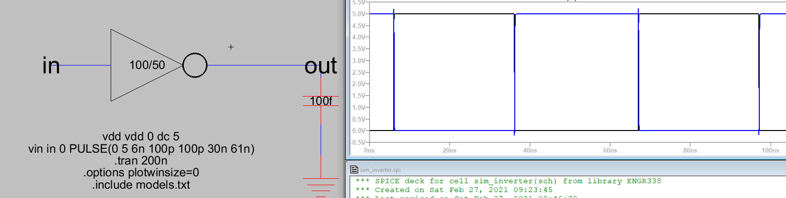
Figure 9. LTSpice simulation of 100/50 inverter driving 100fF cap.
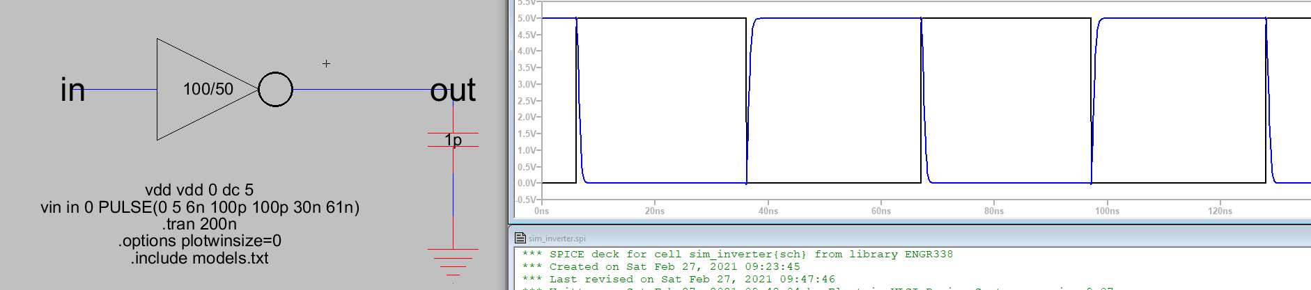
Figure 10. LTSpice simulation of 100/50 inverter driving 1p Cap. Longer
time delay than 100f.
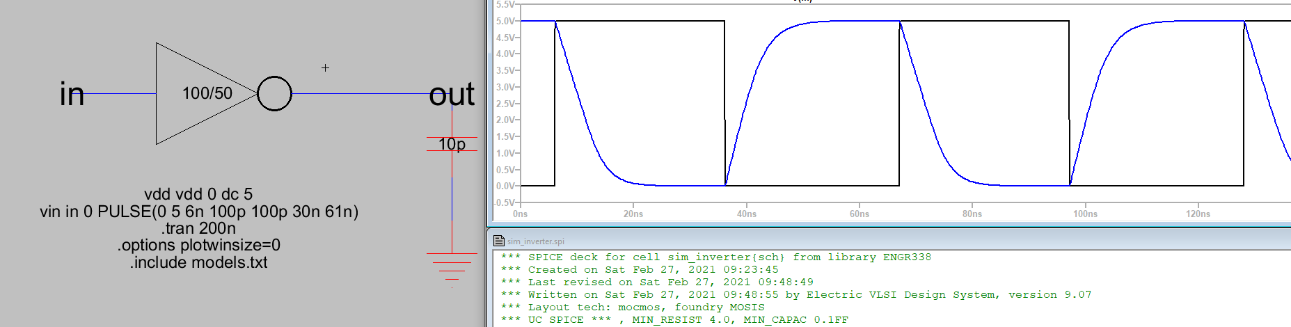
Figure 11. LTSpice simulation of 100/50 inverter powering 10pF cap.
Longer time delay than figure 10, however is able to drive circuit
compared to 20/10 inverter.
Task 5
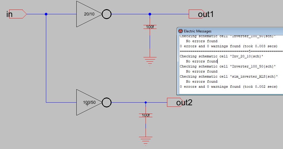
Figure 12. ALS simulation schematic. For use with built in Electric
VLSI simulation tools. DRC clean
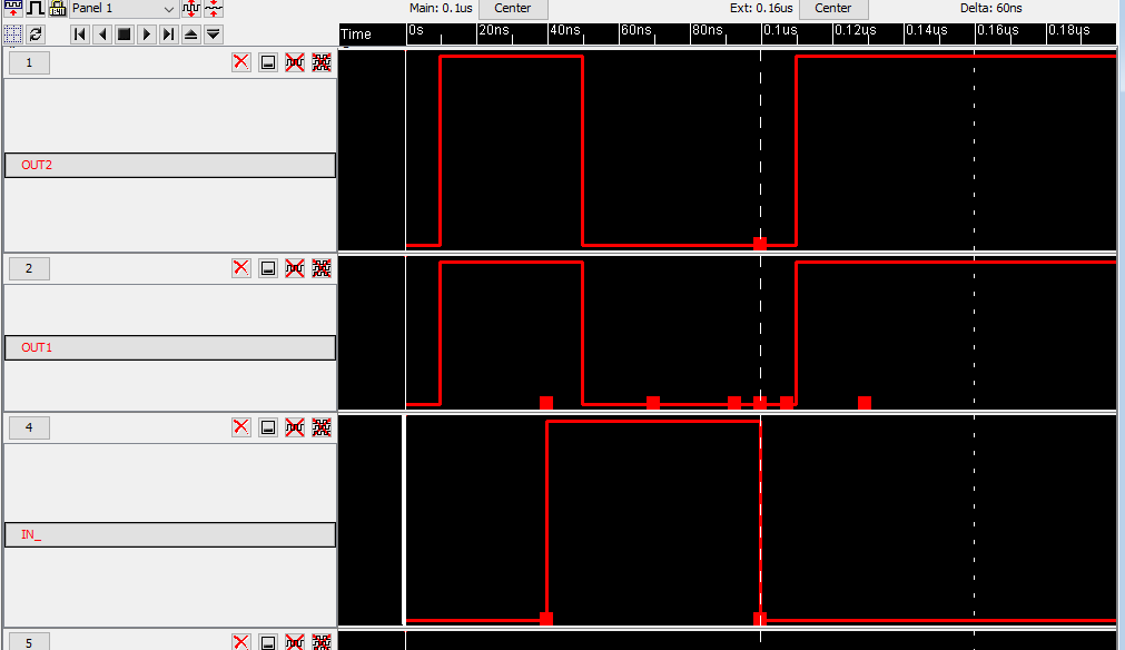
Figure 13. ALS simulation results. Inverted singals for both inverters
that are time delayed from the input by about 10ns.
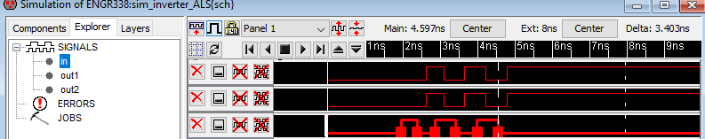
Figure 14. IRSIM simulation of figure 12. There is a noticiable
timedelay between input and ouput of the inverters
Discussion
This lab built more skills in reusing schematics and icons as well as
introuduced us to different simulation tools available. The Muliplier
of the MOS symbols is useful for saving schematic space and preventing
over crowding. The different simulations were interestint to manipulate
high and low signals, but do not appear to be as applicable as LTSpice.
Learning how to use different packages is a good skill to have.