Balancing Robot
Introduction In this project
we will create a robot that stands up right and balances on two wheels.
This robot will use an Arduino powered PID controller to adjust the
onboard motor position to keep the car standing upright when it tilts.
This will first be prototyped using a breadboard and discrete
components but will then be powered by a custom-built PCB.
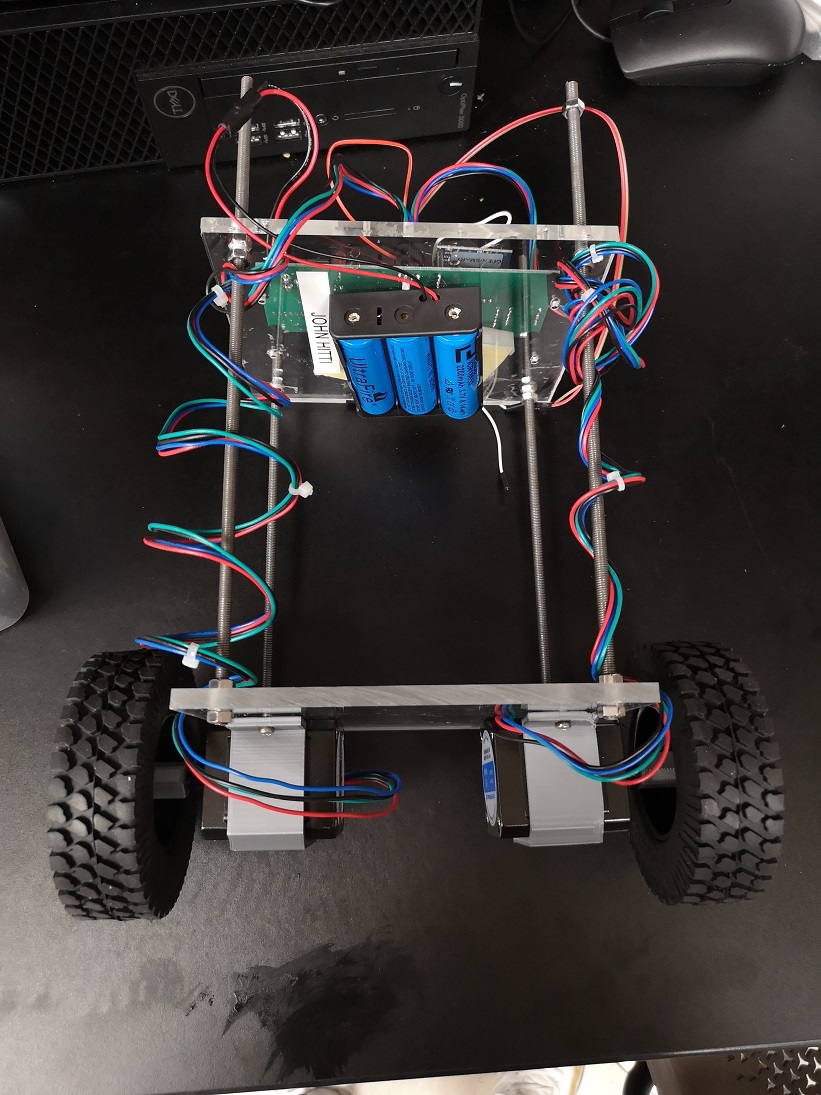
Construction The
construction of the robot consists of two large rectangular slabs of
acrylic plastic. The bottom piece will be used to mount the motors. The
top piece will be used to mount the circuits and batteries. These acrylic pieces are connected using four metal rods with nuts to hold the acrylic slabs in place.
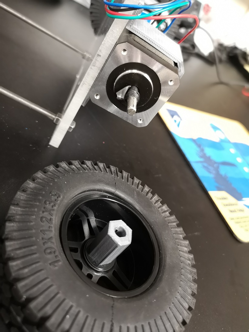
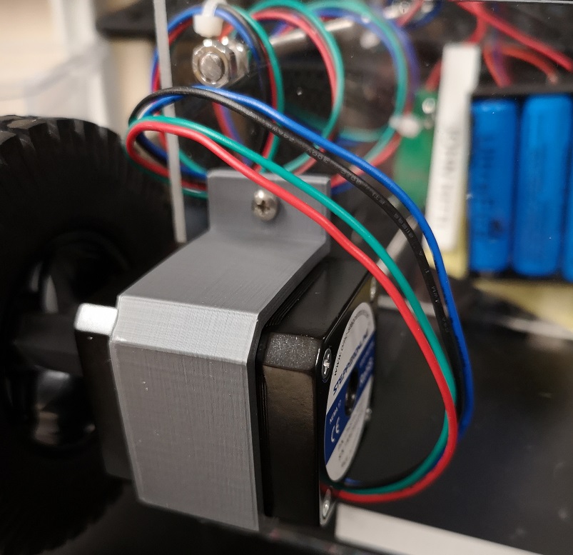
3D printed motor mounts and
wheel mounts were used to attach the motors and wheels to the robot.
The files for these prints can be found here
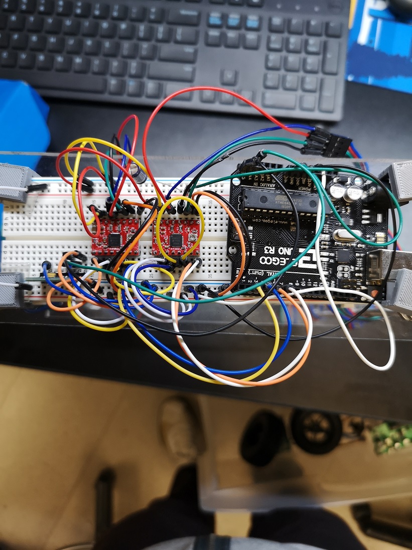
Wiring The
circuitry of the robot is created using a breadboard. This allows for
the design and PID controller to be refined/calibrated before the PCB
phase. Using the breadboard creates some limitations such as an
unreliable accelerometer reading as well as many potential loose
connections.
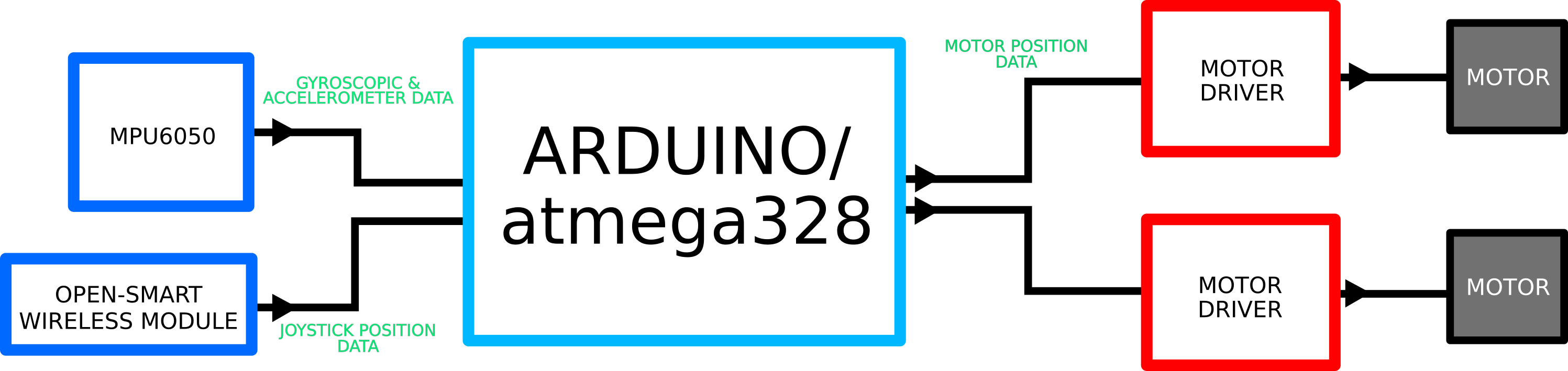
The robot is controlled by an
Arduino in the configuration described below. The Arduino reads data
from the accelerometer and then calculates the appropriate response to
send to the motor drivers. The open-smart wireless module is connected
to allow for an external remote controller. A more in depth connection
diagram is displayed below in the PCB section.
Code The code for the Arduino to run is here.
This code allows the Arduino to perform two functions at once by using
the ISR interrupt. This allows it to calculate the PID output and
adjust the position of the motors with only a single core. The user
must specify an accelerometer calibration value as well as the gain
values for the PID component. A proper accelerometer calibration value
will allow the robot to hold a stable starting angle that won’t drift
to one side or the other. Proper PID gain values allow the robot to
accurately adjust itself as it's angle changes. These gain values must
be set so the robot neither overshoots nor undershoots past the desired
output value, which will cause instability. During this project I
worked with Nick Llarena. Below is a video of his robot running the
code with calibrated values specific to his build.
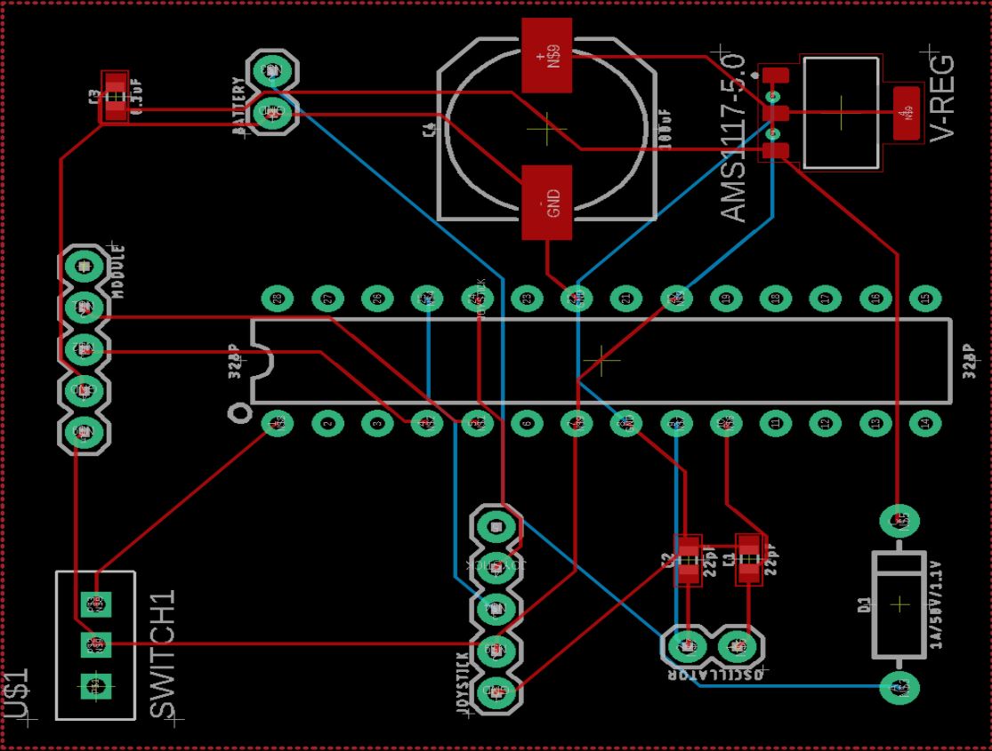
PCB Once
our robots were built we were tasked with taking our breadboard
circuitry and constructing a PCB to house all the components. This
offers lots of benefits for the operation of the robot including: a
stable MPU6050 output, increased connection durability, and an overall
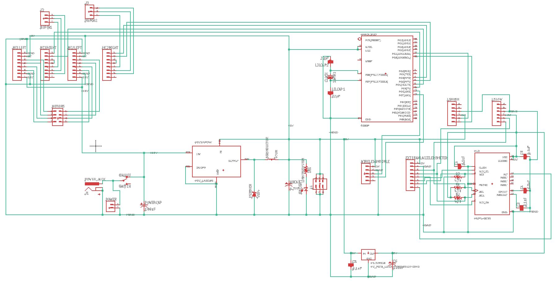
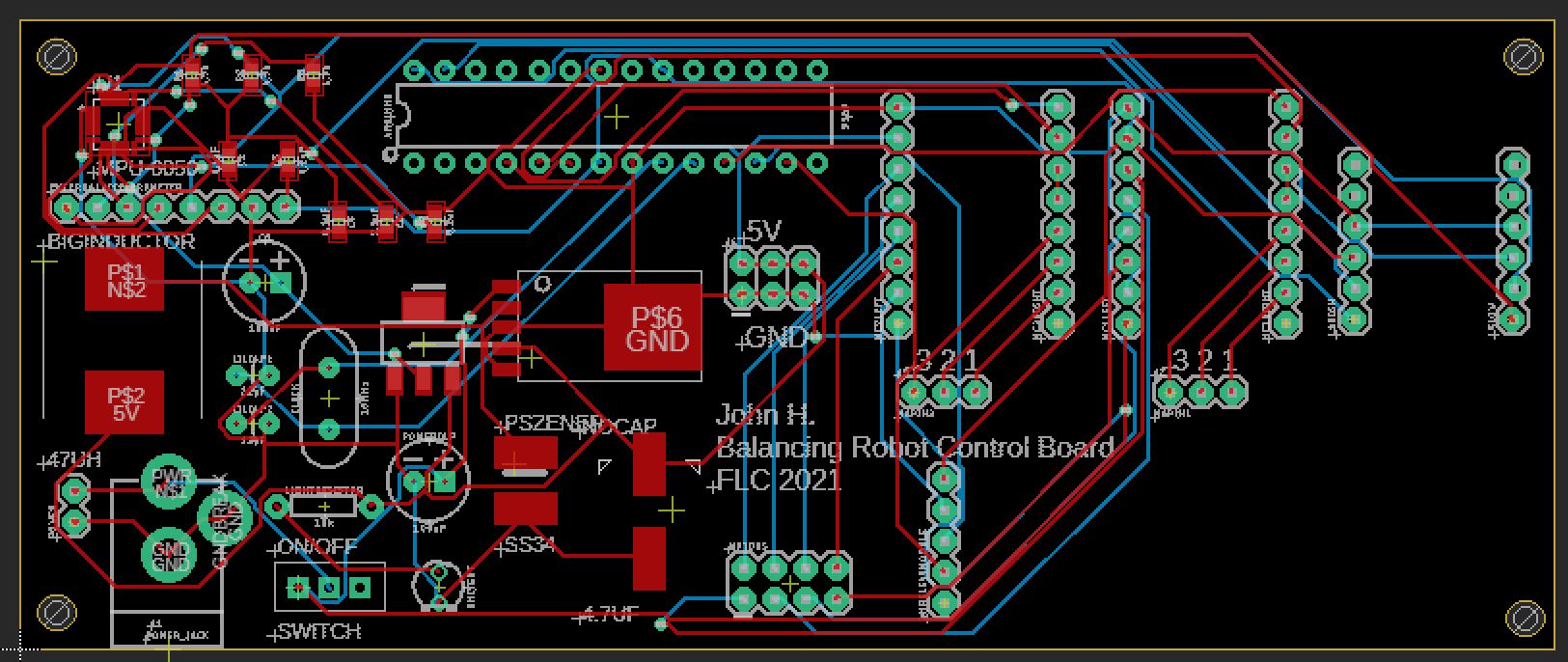
cleaner final product. The PCB was designed in EAGLE PCB and the files
for the final PCB are here.
The PCB features all the
components from the breadboard. However, the MPU6050, atmega328p, and
their required discrete components are soldered directly to the board
instead of using the typical breakout board configuration. A level
shifter breakout board was also added to the MP6050 to ensure the data
input was an appropriate 3.3v and not 5v. This board was designed with
several "quality of life" aspects in mind. The board has two different
types of power connections for different needs. The board also contains
header pins for the motor driver configuration pins to adjust them as
needed. Finally, if it is not desirable to solder the MPU6050 directly
to the board there are built in pin holes for an external breakout
board version to be connected.
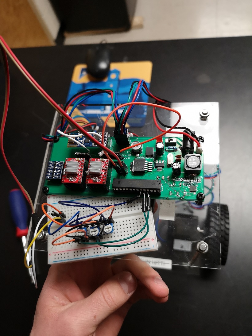
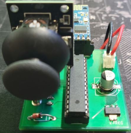
Once the board was manufactured it was added to the robot and tested
for functionality. When building the board, it was found that the
MPU6050 was quite hard to solder directly to the board. After a few
attempts it was connected successfully. Once the appropriate
acceleration calibration values and PID gain vales were added the robot
worked as expected!
During this process there were many problems encountered that needed
troubleshooting. The first was there was no effective way to
communicate with the atmega328p. When the chip was connected to the
Arduino, we could interface with it using the serial monitor. Since
this functionality was not built into the PCB, we had to remove the
chip anytime we wanted to re-program it. Fortunately, the accelerometer
could be programmed by bridging the TX and RX serial pins on the
Arduino board to the chip-less robot PCB. This method seemed to work
fine however a better way to calibrate the robot would be optimal.
Another major issue was the inability to effectively define the PID
gain values without removing the atmega328p chip. To combat this, a
small breadboard with three potentiometers was added to the robot.
These potentiometers would change the PID gain values within a range of
values that were known to give good results.
This allowed us to tune the
PID controller to an acceptable value. It was still very difficult to
effectively select a good value and I would recommend tuning the PID
controller completely before replacing the breadboard with a PCB.
Another problem that was encountered were loose wheel connectors. The
motors were not properly connected to the wheels which resulted in a
lot of play in the connection which resulted in instability.
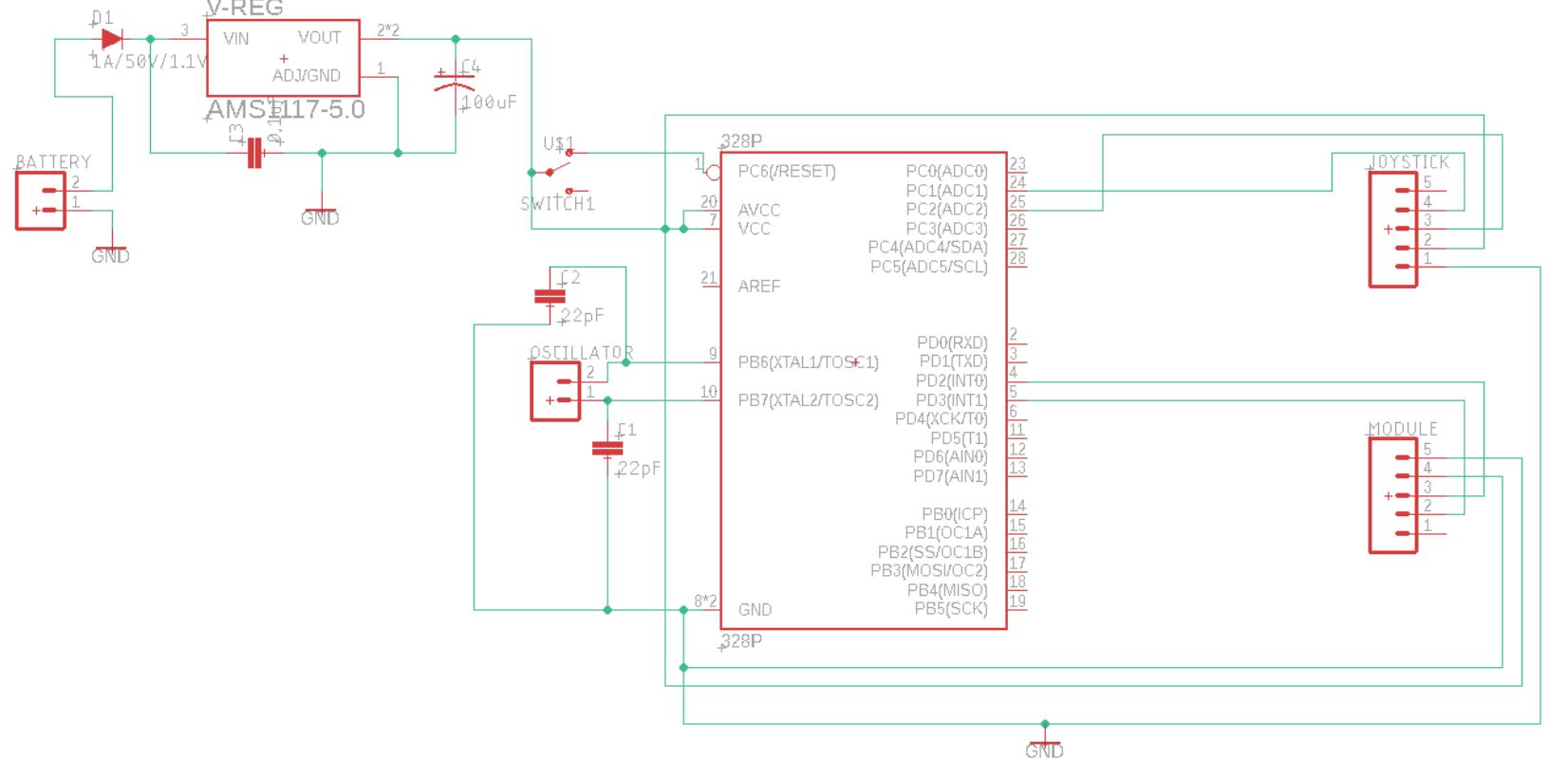
Joystick An
additional component added to robot was the ability to control the
direction with a simple joystick. This was done by using a second
microcontroller to read the position of a joystick and transmit the
data over the wireless receiver connected to the robot. This was first
done by prototyping the circuit on a breadboard and then was
constructed using a PCB. The EAGLE PCB files are located here. The code for the joystick can be found here.
Once the joystick was built
it was tested for functionality and worked as expected. The joystick
was not yet implemented into the operation of the robot.
Discussion Overall
this project was an excellent introduction into more advanced robot
design. It built on a lot of acquired knowledge throughout the class as
well as previous classes here at Fort Lewis. The opportunity to work on
this robot helped build a lot of skills surrounding designing and
constructing microcontroller circuits with more complex controll
systems. This project taught many of these skills in a hands-on way
that led to a deeper understanding of these systems and components and
how they may be used in a real world setting.