John Hitti
Final Project
CE 351 Microcontrollers
11/16/2020
Introduction
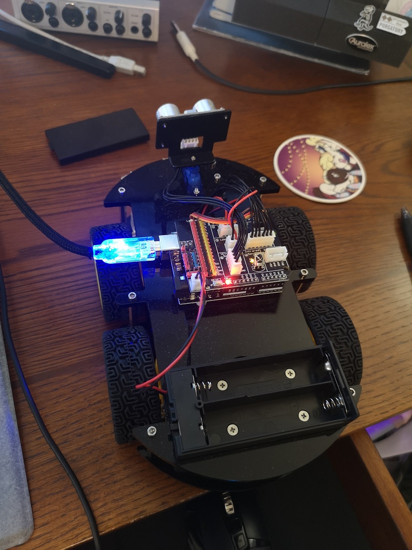
In our final project we worked with the Elegoo Smart Car Kit 3.0v. This robot car kit contains a microcontroller powered robot with numerous sensors to allow it to traverse different terrain. Equipped to this robot is an ultrasonic sensor, motors, IR emitters/receivers, a servo, and another IR sensor to allow for remote control commands. Using all of these sensors we will attempt to program this robot to take commands from a remote, follow lines, and avoid obstacles.
TASK 1
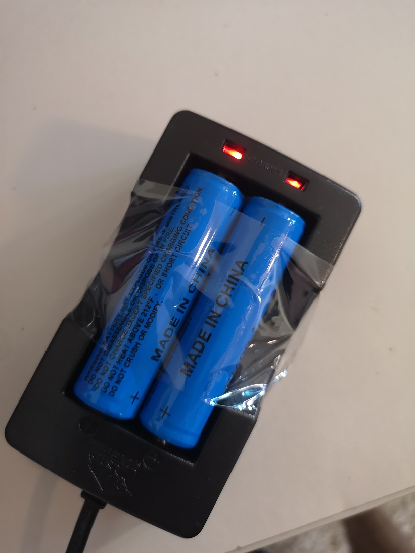
In this task we were directed to assemble the car. Since our car already came preassembled we took the time to tighten all the bolts and screws. We took time to go over the instructions to make sure our car was assembled properly. The included batteries were also charged.
Figure 1. The robot is connected to the computer via USB while the batteries charge
TASK 2
In this task we tested the ultrasonic sensor included with the robot. The sensor outputs the distance of an object in front of it using ultrasonic waves. This allows for a distance measurement from 2-400cm with an accuracy of 3mm which is perfect for detecting barriers in front of our moving robot.
Video 1. A test sketch is loaded to the Arduino to test the distance from the sensor to the book.
TASK 3
In this task we ran a sketch to test our servo. The ultrasonic sensor is attached to this servo and allows it to measure distance in a 180-degree arc in front of the robot.
Video 2. A test sketch is loaded to the Arduino to test servo functionality.
TASK 4
In this task we ran a sketch to test the motor functionality. All four wheels on the robot are driving by a L298 Dual H-Bridge Motor Driver module . This module can power two DC motors at 2A. We can control the speed of these motors by using PWM from the Arduino to the driver module.
Video 3. The robot motors are tested
TASK 5
In this task we ran a sketch to test the line tracker sensors. These sensors are made up from three different IR sensor/emitter pairs. These are spaced out in a line and can determine the position of a black line underneath the car.
Video 4. The line tracker sensors are tested
TASK 6
In this task were instructed to code Mode 1 of the final car program. This final program is controlled by an IR remote which sends signals to an IR Sensor on the robot. Pressing 1 on the remote will enable mode 1. In mode one the arrow keys act as controls for the robot as seen in Video 5. The code for this mode can be seen below in Figure 4 and 5.
Video 5. Mode 1 is enabled and all directions are tested
TASK 7
In this task we instructed to add Mode 2 to our code. Mode 2 utilizes the line tracker sensors to allow the robot to follow a solid black line. This can be seen in Video 6 below when mode 2 is enabled by pressing the 2 button on the remote. Figure 4 displays the code that drives the sensors.
Video 6. The line tracker sensors are tested
TASK 8
Our final task was to add Mode 3, an obstacle avoider mode, to the robot. Using the ultrasonic sensor, the robot had to drive forward and turn out of the way when an obstacle was nearing. This can be seen below in Video 7 and the code that drives this can be seen in Figure 4.
Video 7. The line tracker sensors are tested
The Arduino code for all three modes is displayed below in order.
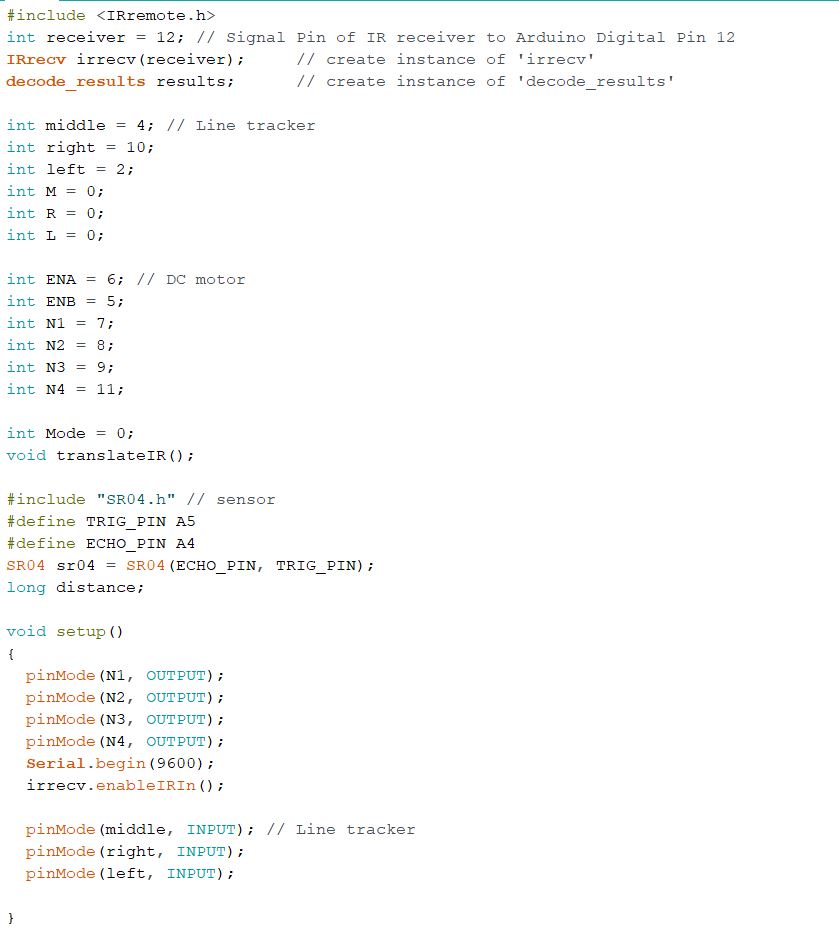
Figure 2. Code setup and variable declaration
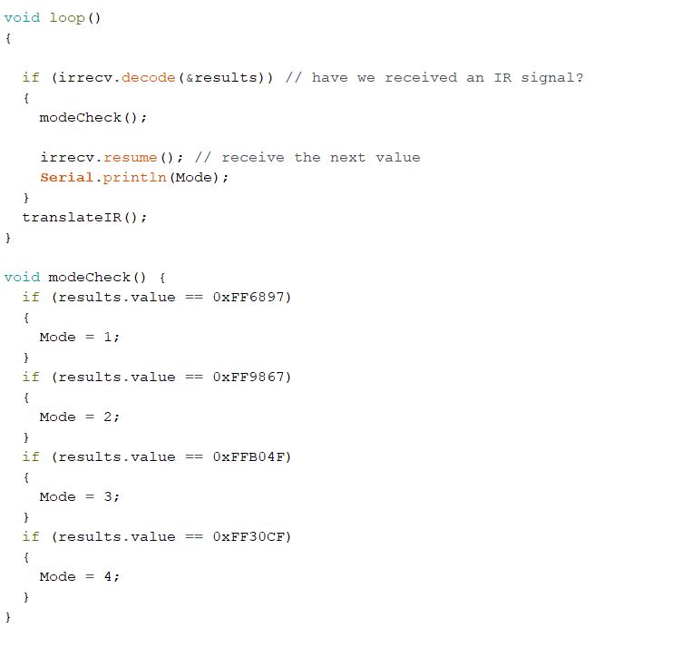
Figure 3. Code loop function and mode check function
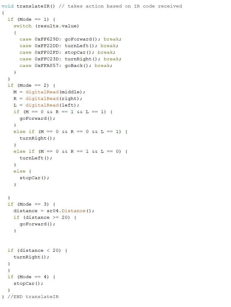
Figure 4. Translate IR function responsible for telling the robot what to do based on the button pressed
utilizes
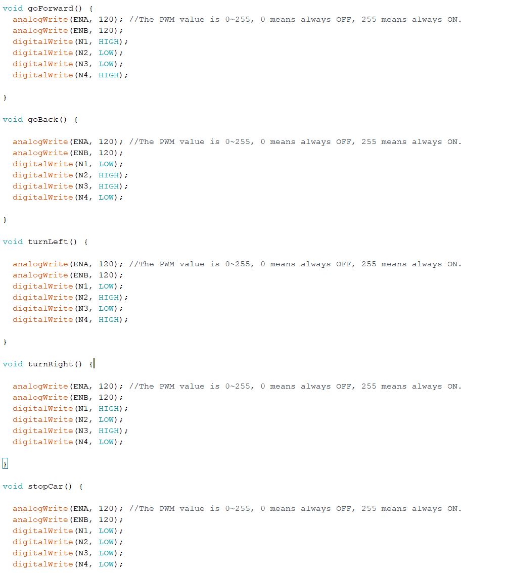
Figure 5. Driving functions that control the direction of the motors
Discussion
Overall this project was an excellent conclusion to the microcontrollers class. This project tied in many of the skills learned in the other labs and also help familiarize us with the concept of tying these skills together. Robotics is a very important field in computer engineering and this is an excellent introduction to the basics of programming robots and microcontrollers.