PID Control
CE351 2020 Fall
John Hitti
jdhitti@fortlewis.edu
Introduction
In this lab we were directed to create a PID controller using a LED and a photocell sensor. The photocell has a large resistance in the dark which goes down in the presence of light. This can be used to measure the amount of light in a given area. This is combine with an LED to create a feedback loop control system that will adjust the amount of light on the sensor accordingly.
TASK 1
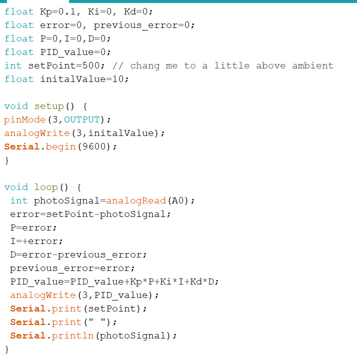
In task one we were directed to code the PID controller. Once the code is loaded on the Arduino we can see a serial output that shows the sensor adjusting the LED to match the desired set point.
Figure 1. The code for driving the PID Controller
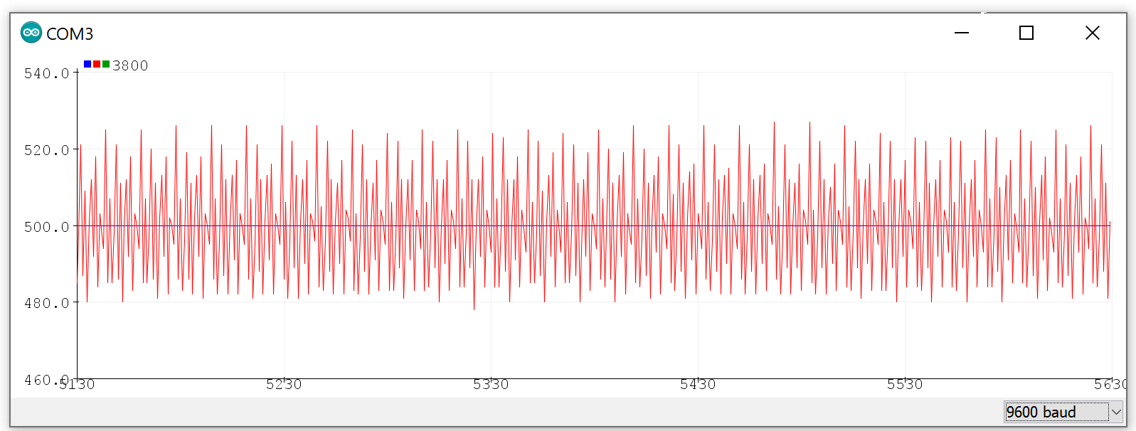
Figure 2. The input from the sensor oscilating around our set point of 500
TASK 2
Using an external LED we are able to test our PID Controller's ability to react to changes in ambient light. Turning on and off an external LED allows the controller to react and adjust the controller led to return to the appropriate set value.
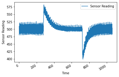
Figure 3. A plot representation of our sensor input when changing the ambient light amount
TASK 3
In this task a button is used to adjust the set value by increments of 20 starting at 500. Once the button is pressed and the value is changed the sensor will adjust itself to settle around the new value.
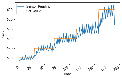
Figure 4. A plot representation of the changing set value from 500 to 600
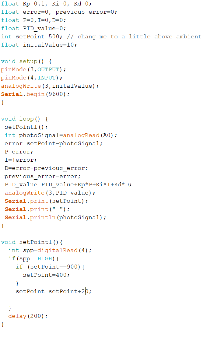
Figure 5. The code used to drive the PID controller and adjust the set value.
Discussion
This
lab is an excellent introduction into the functionality of PID
controllers and their application with microcontrollers. Although this
example is simple and straightforward the application of a control loop
mechanism that employs feedback can be very useful in the field of
mechanical and robotic engineering. These concepts could be applied to many different applications.