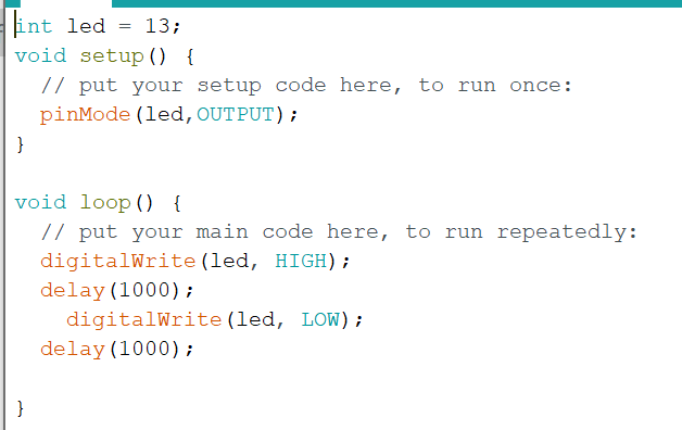
Figure 1. A simple code to blink the onboard Arduino led
LEDs and SSDs
CE351 2020 Fall
John Hitti
jdhitti@fortlewis.edu
Introduction
In
this lab we learned
about the functionality of LEDs and SSDs and how they can be used with
the Arduino. The tasks completed in this lab show many of the different
ways to control these devices using code, buttons, decoders, and shift
registers.
LEDs
TASK 1.1
Our first task was to write a code
that would blink the onboard LED.
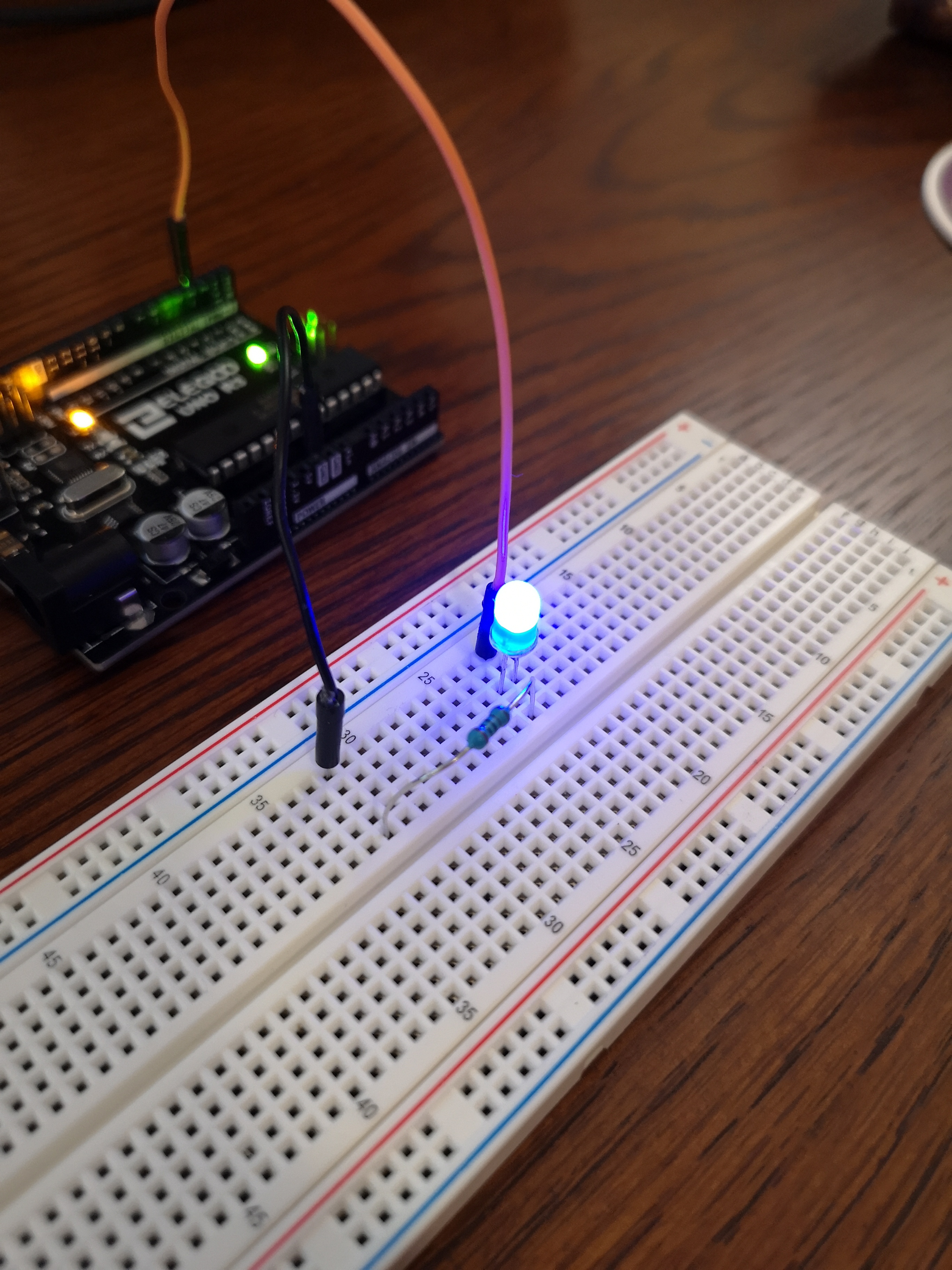
TASK 1.2
By changing the output pin from the onboard LED to a different pin we are able to make our own led light up.
TASK 1.3
We can alter this code to
allow multiple LED's to light up. Each one delayed by a fraction of a second.
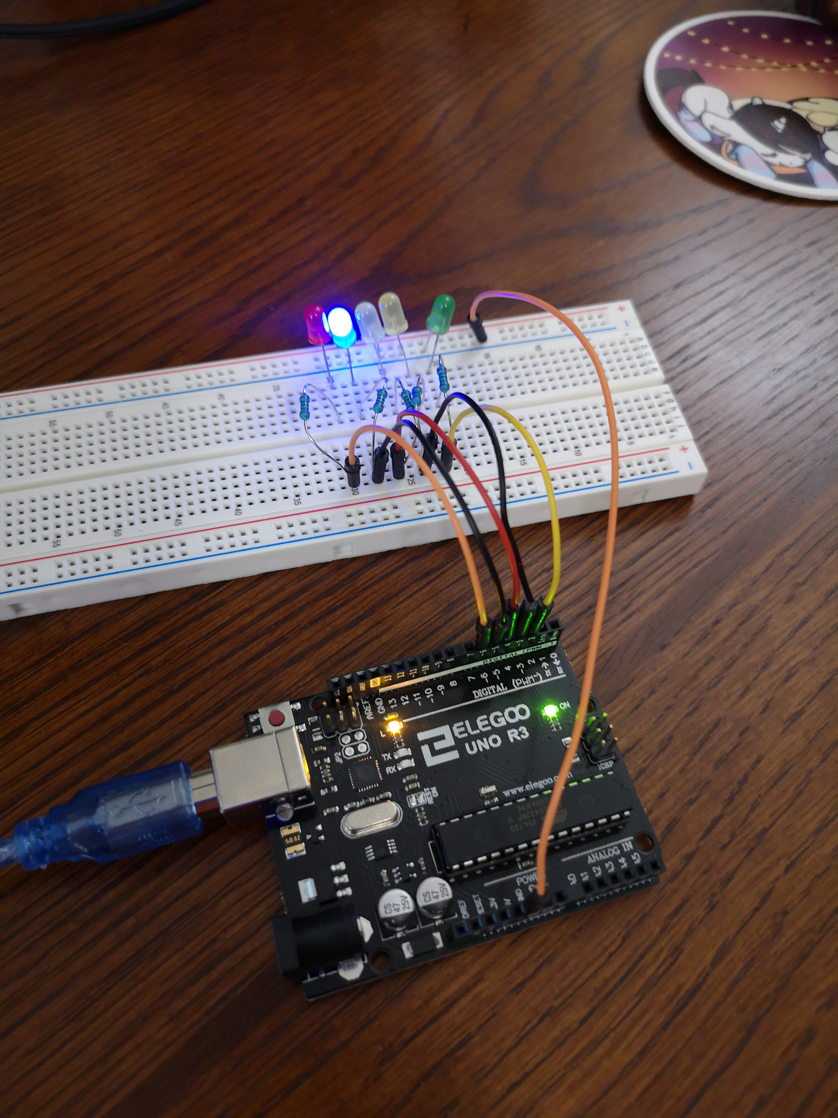
Figure 3. An array of LEDs Lighting up
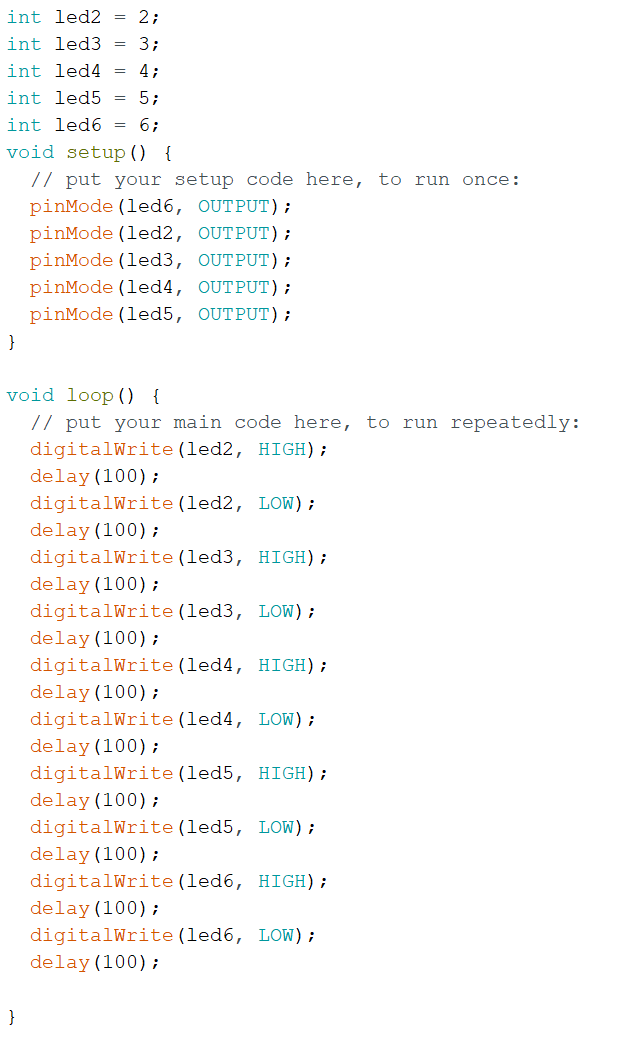
Figure 4. The code to drive the LED array
TASK 2.1
Using a pushbutton we can code the Arduino to respond to this input by lighting up the LED
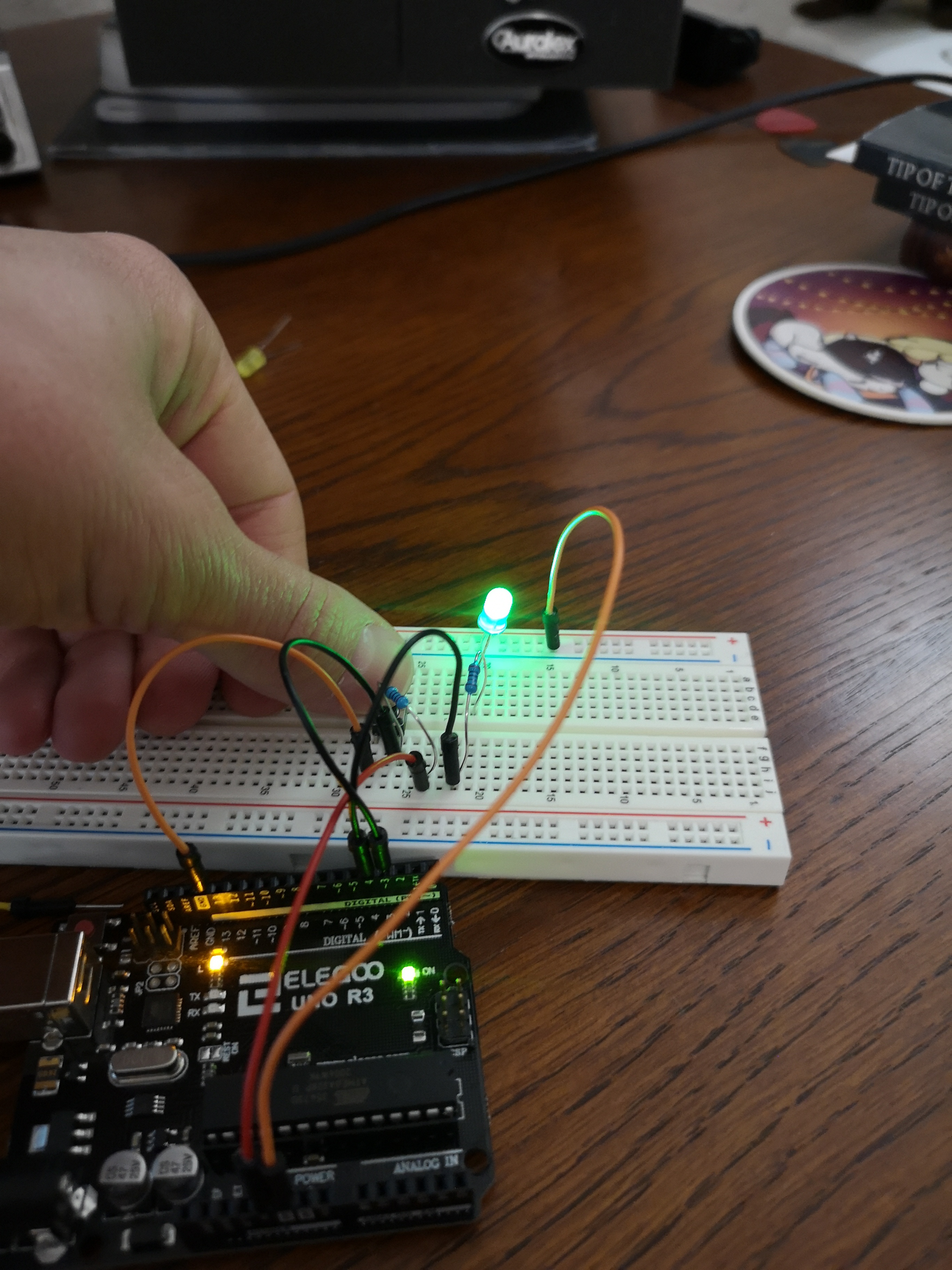
Figure 5. A pushbutton is used to light up an led
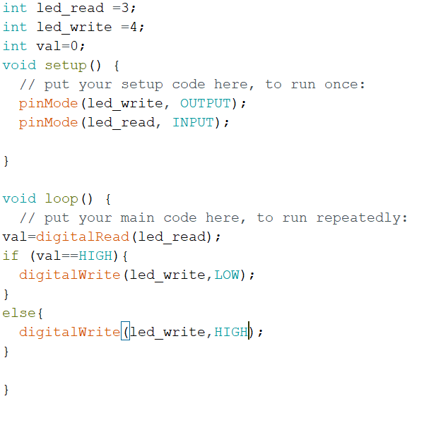
Figure 6. The code used to turn on and off the LED via a switch
TASK 2.2
The arduino can also be programmed to power off the LED when the button is pushed.
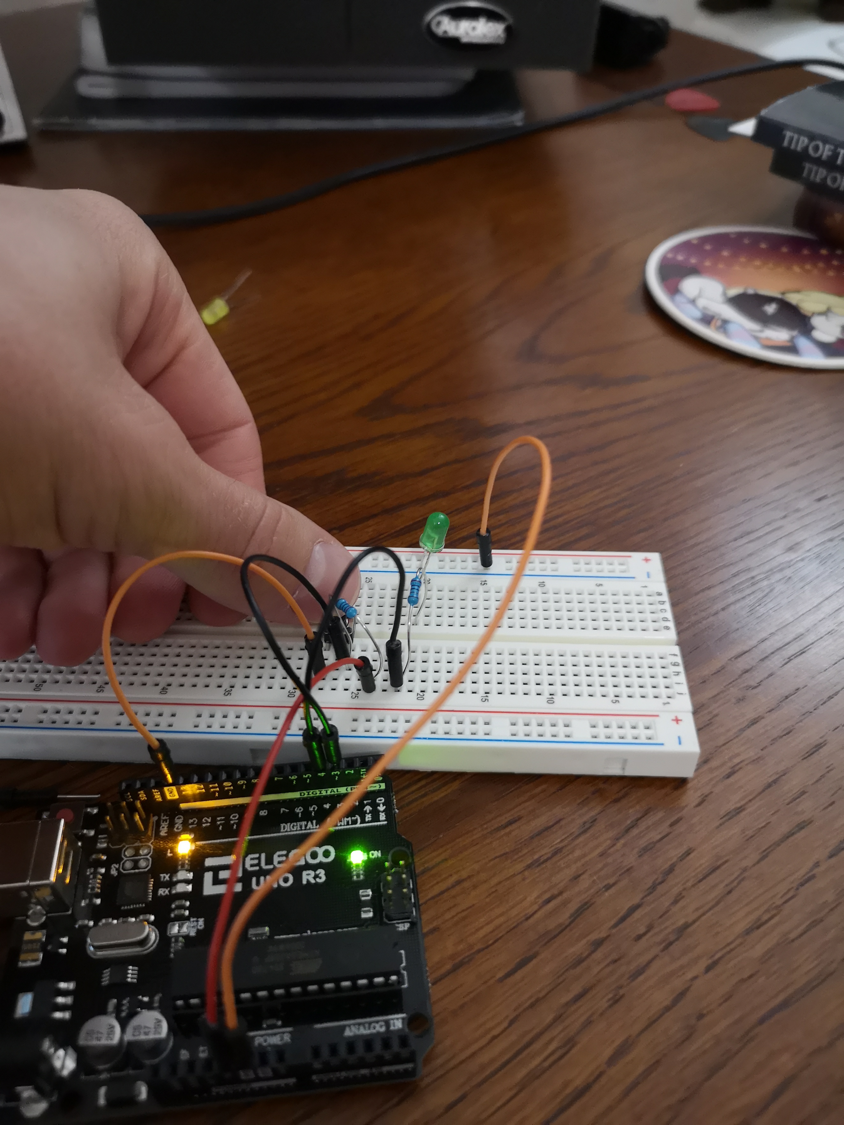
Figure 5. A pushbutton is used to tell the Arduino to power off the LED
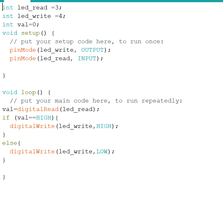
Figure 6. The code used to turn on and off the LED via a switch
TASK 2.3
In this task the arduino was coded to blink the LED for one second after the button was pressed.
Figure 7. A video showing the led blink for a second after the button is pressed
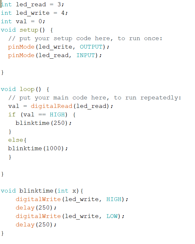
Figure 8. This code tells the Arduino to blink the LED for one second after the button is pressed.
TASK 2.4
By modifying our code in 2.3 we are able to change the rate the LED blinks at by pressing the pushbutton.
Figure 9. A video showing the change of blink rate when the button is pressed
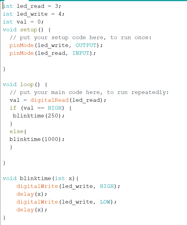
Figure 10. The code that arduino runs to perform the blink sketch
SSDs
TASK 2.1
In this task we were instructed to familiarize ourselves with the "Seven-Segment Display" (SSD). This device is similar to an array of seven LEDs and was set up to show various decimal numbers. Unfortunately during this process the lower right segment resistor was accidentally shorted and blew out the internal LED. Despite this it was still possible to complete the following tasks.
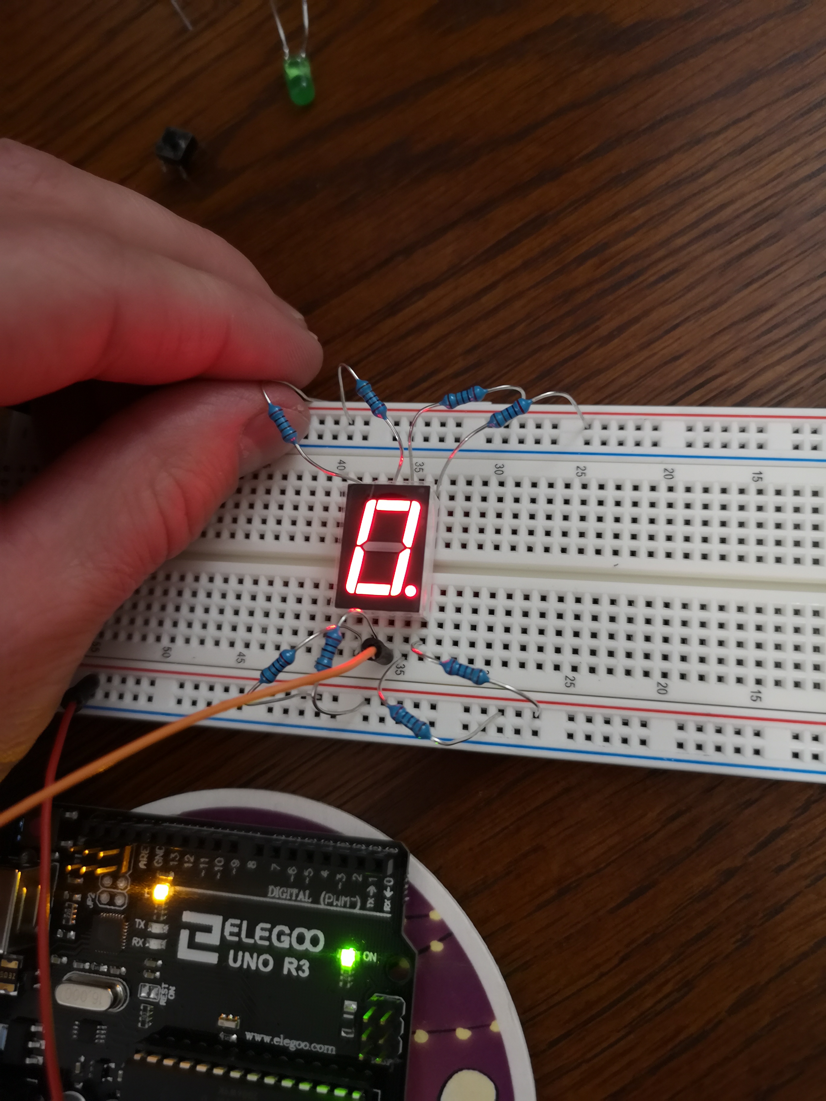
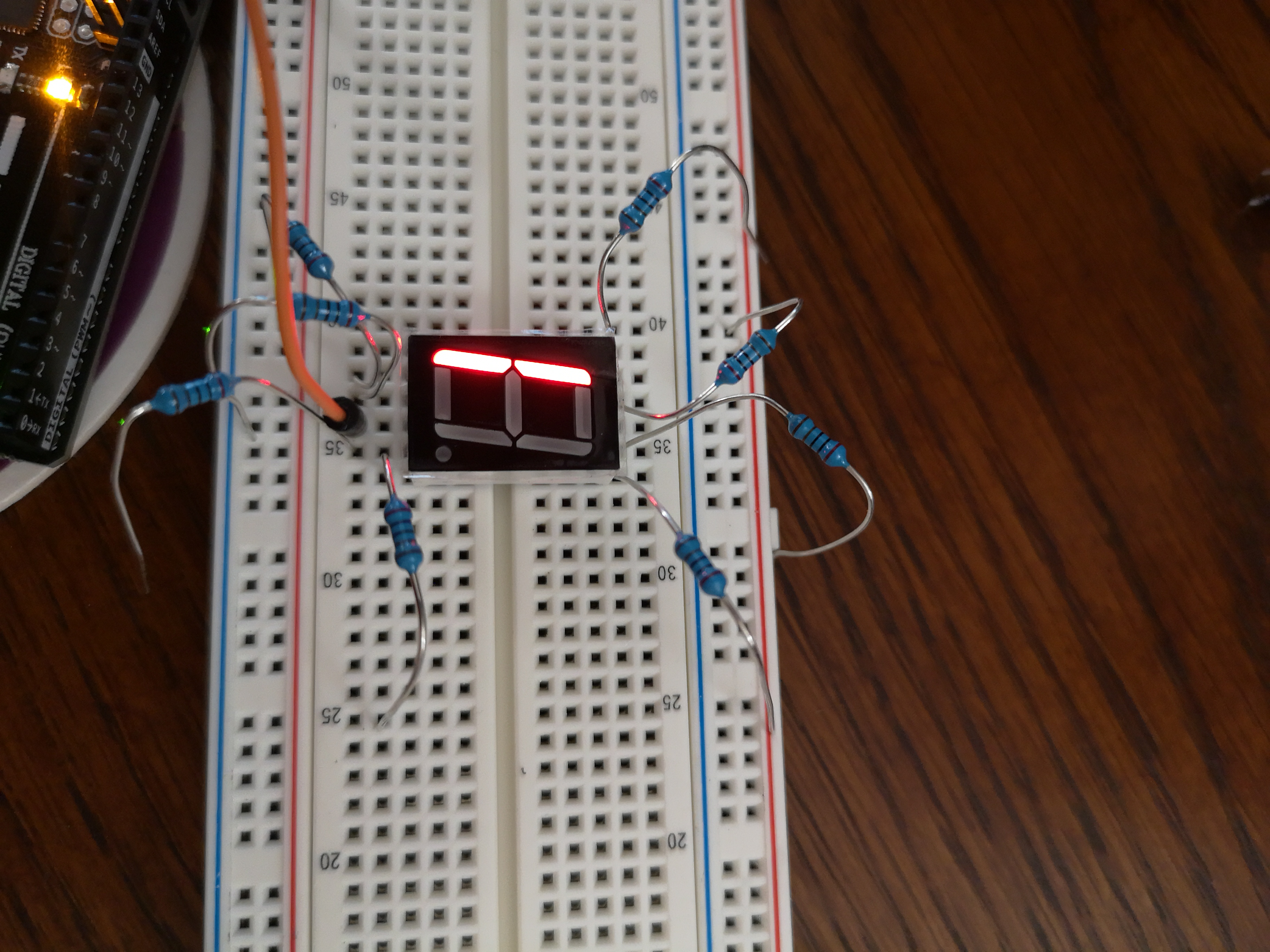
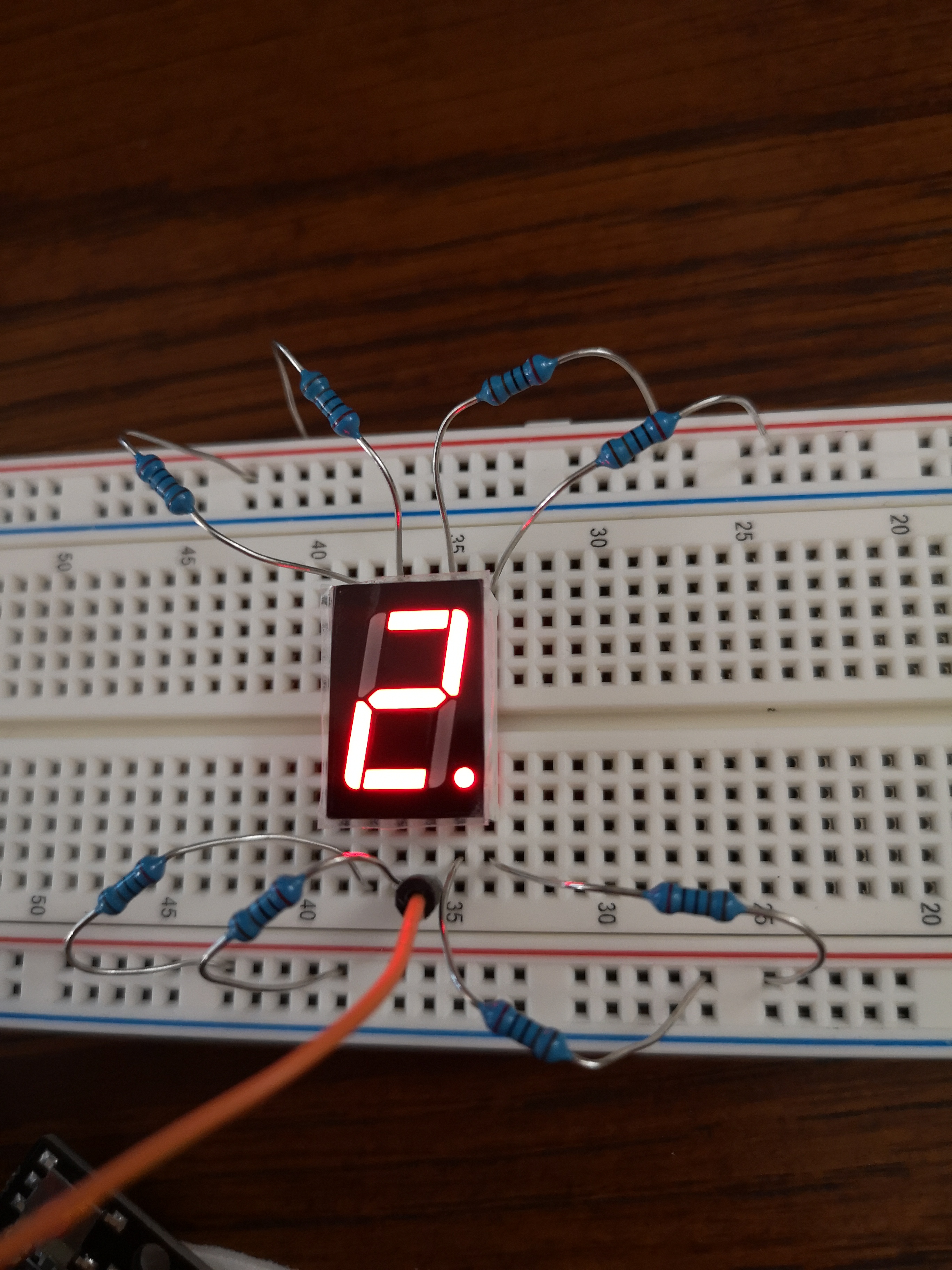
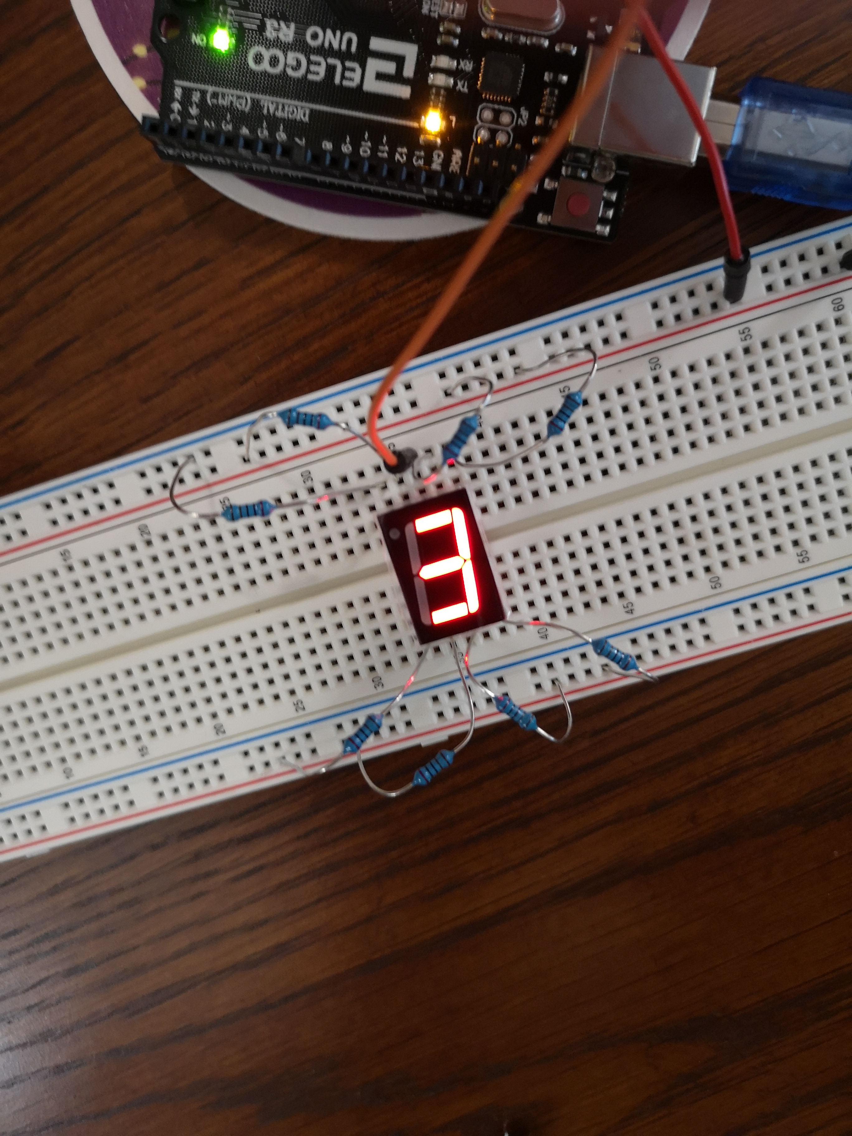
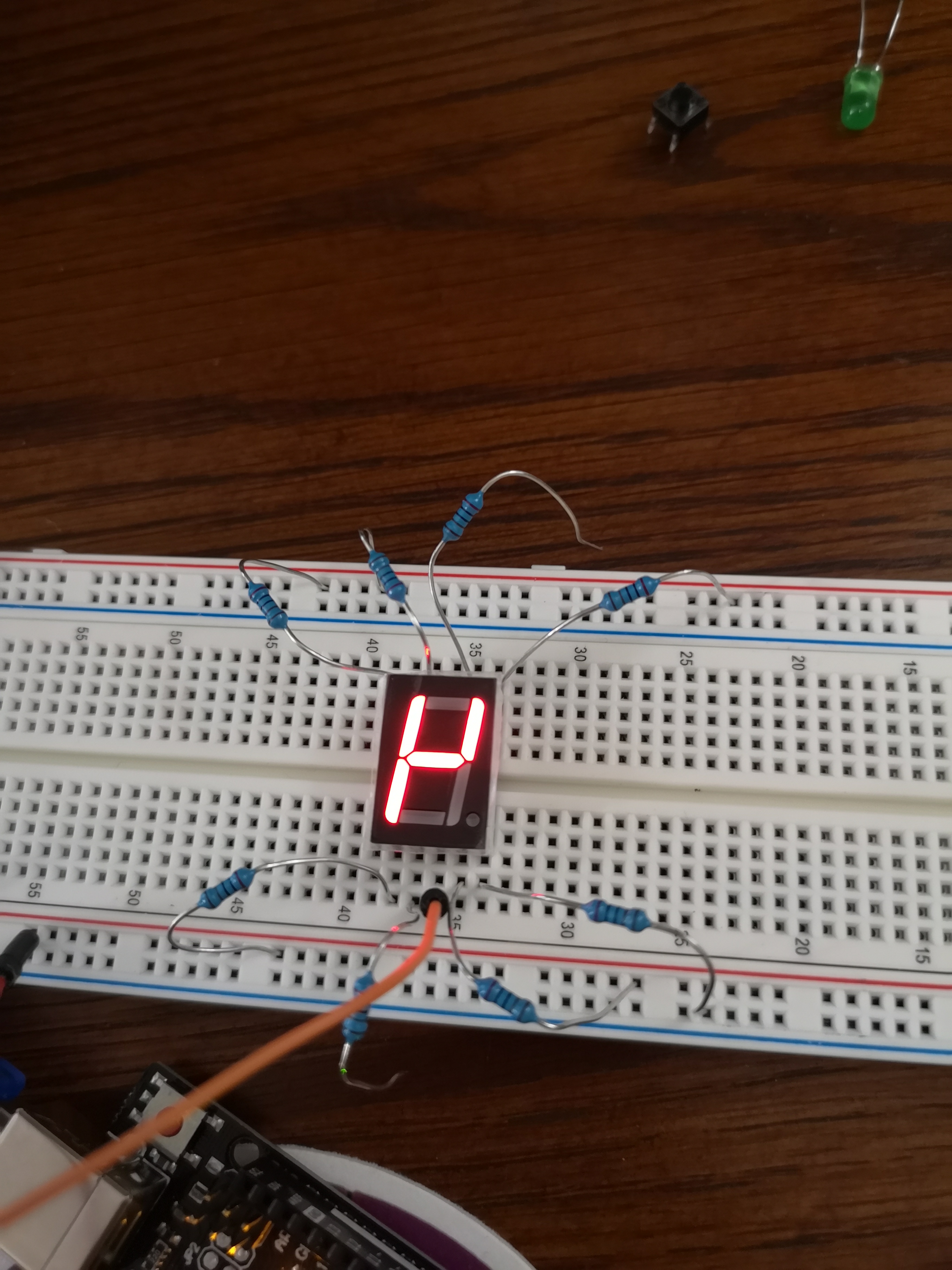
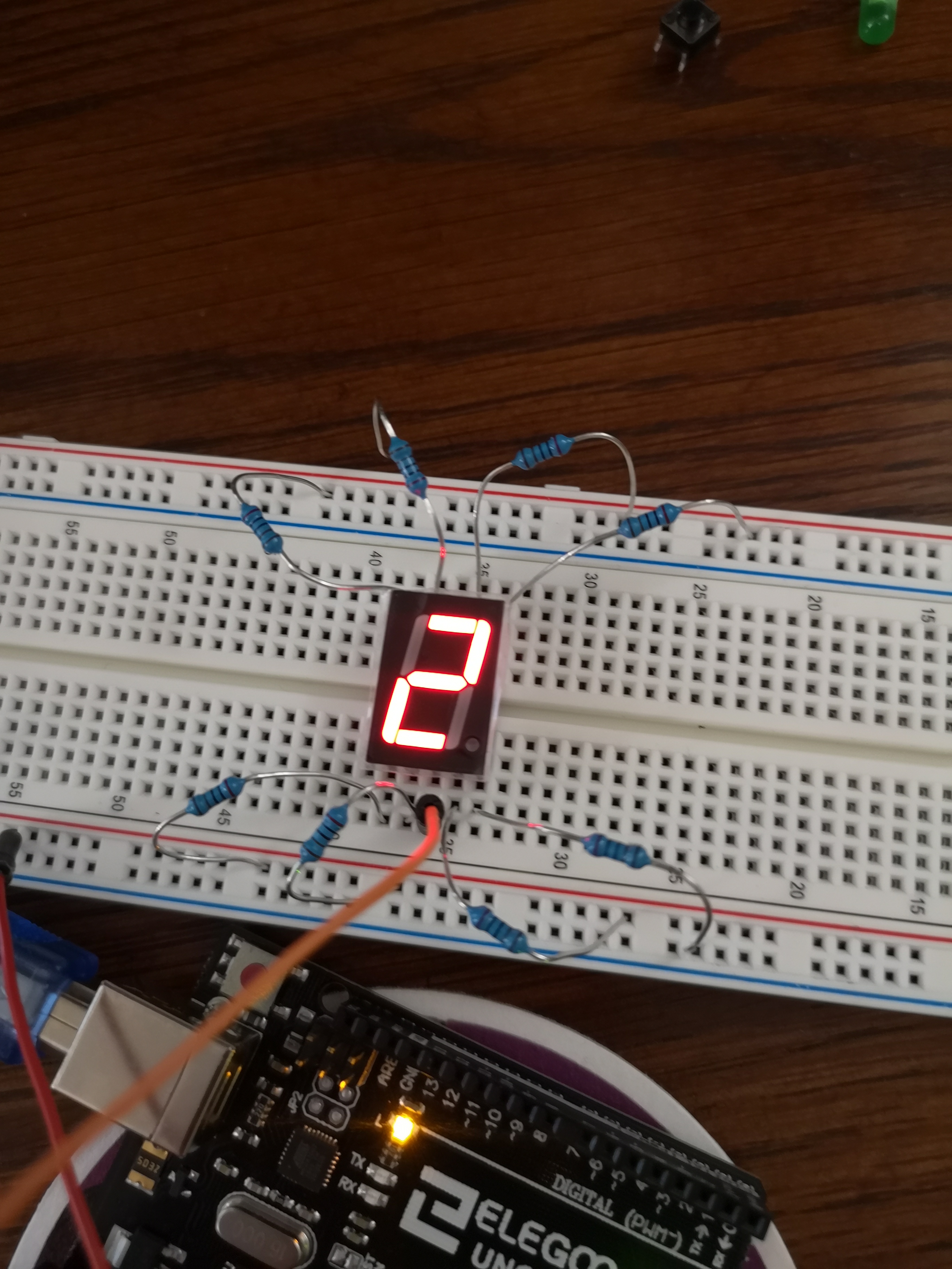
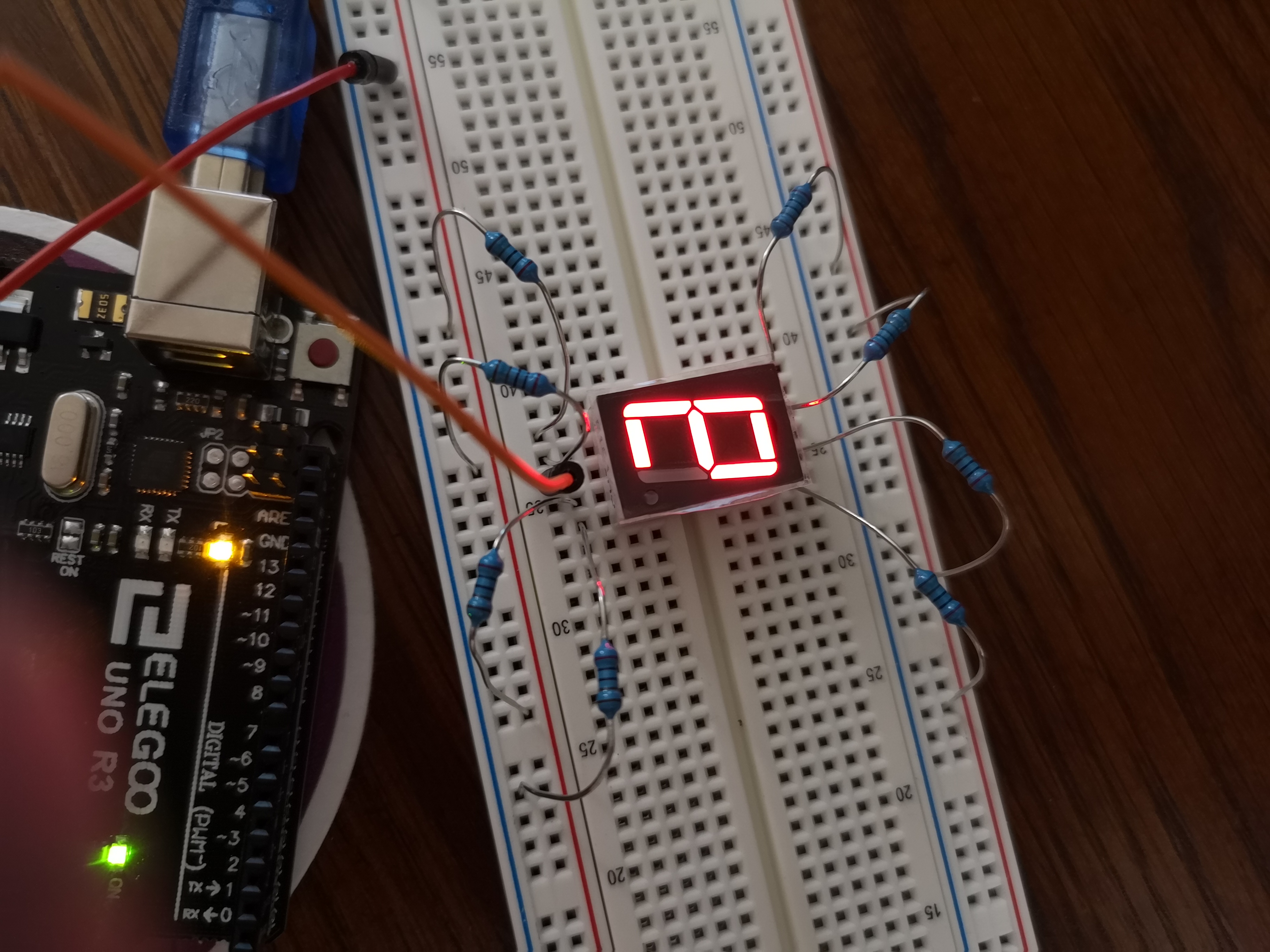
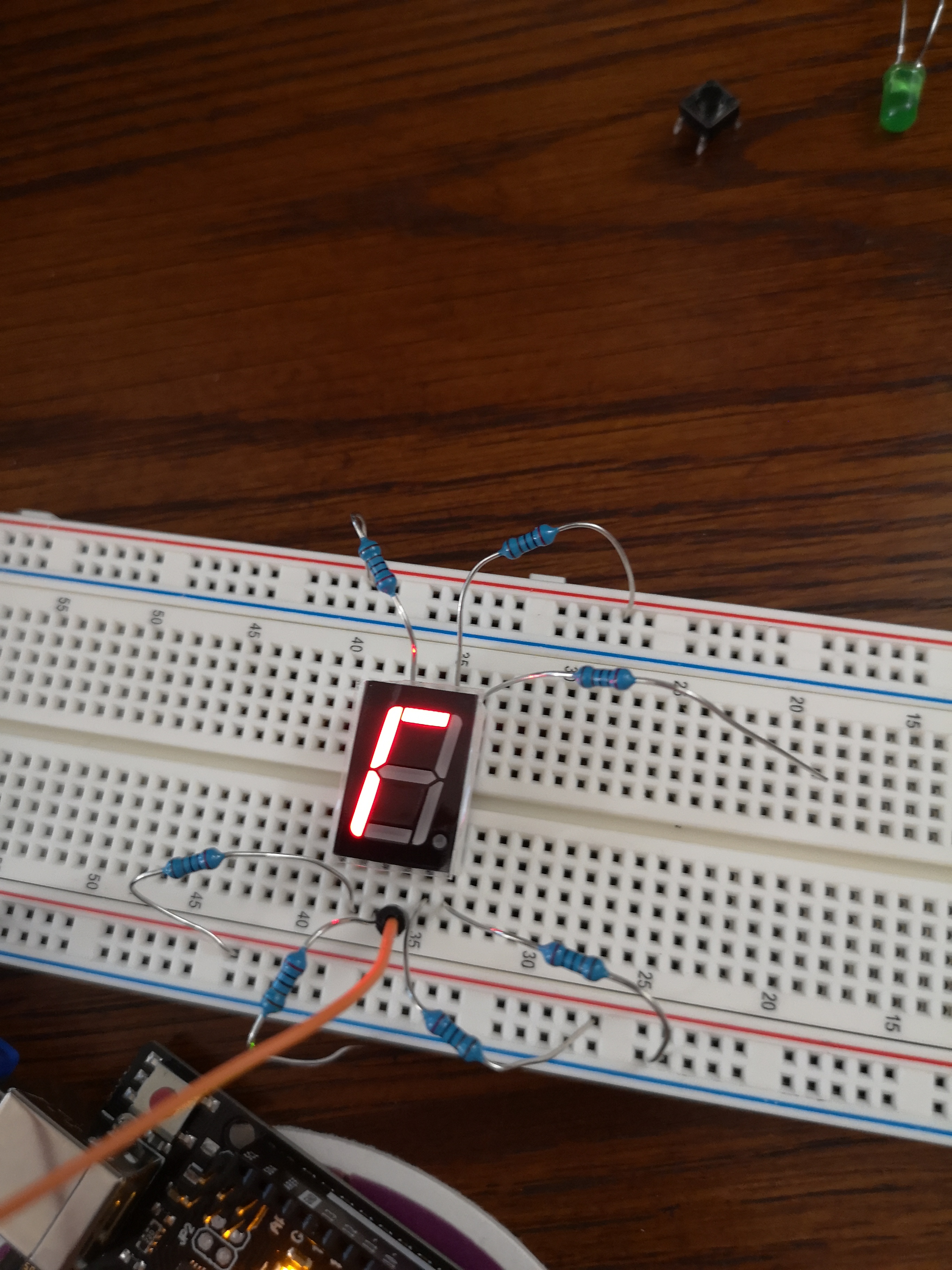
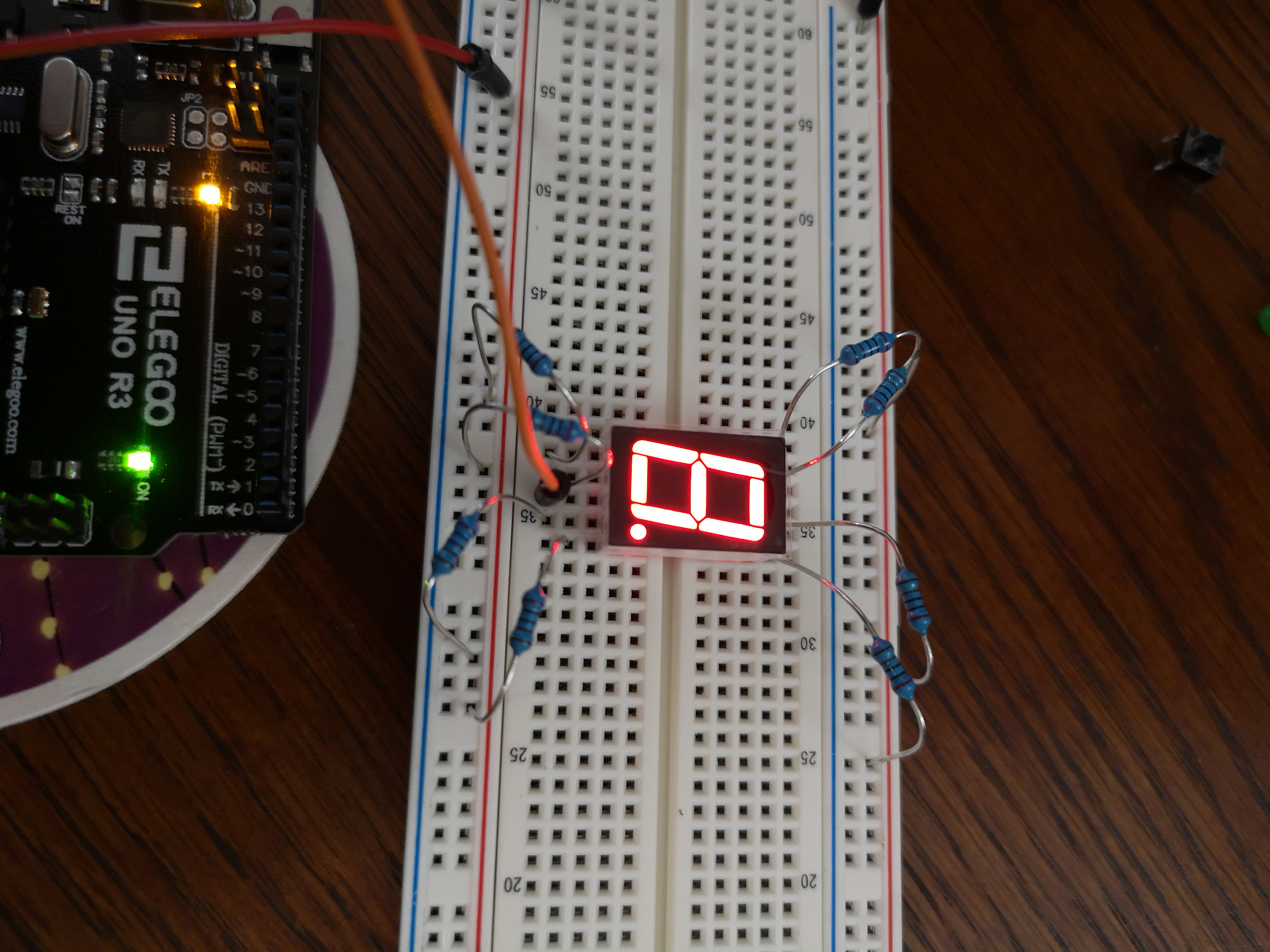
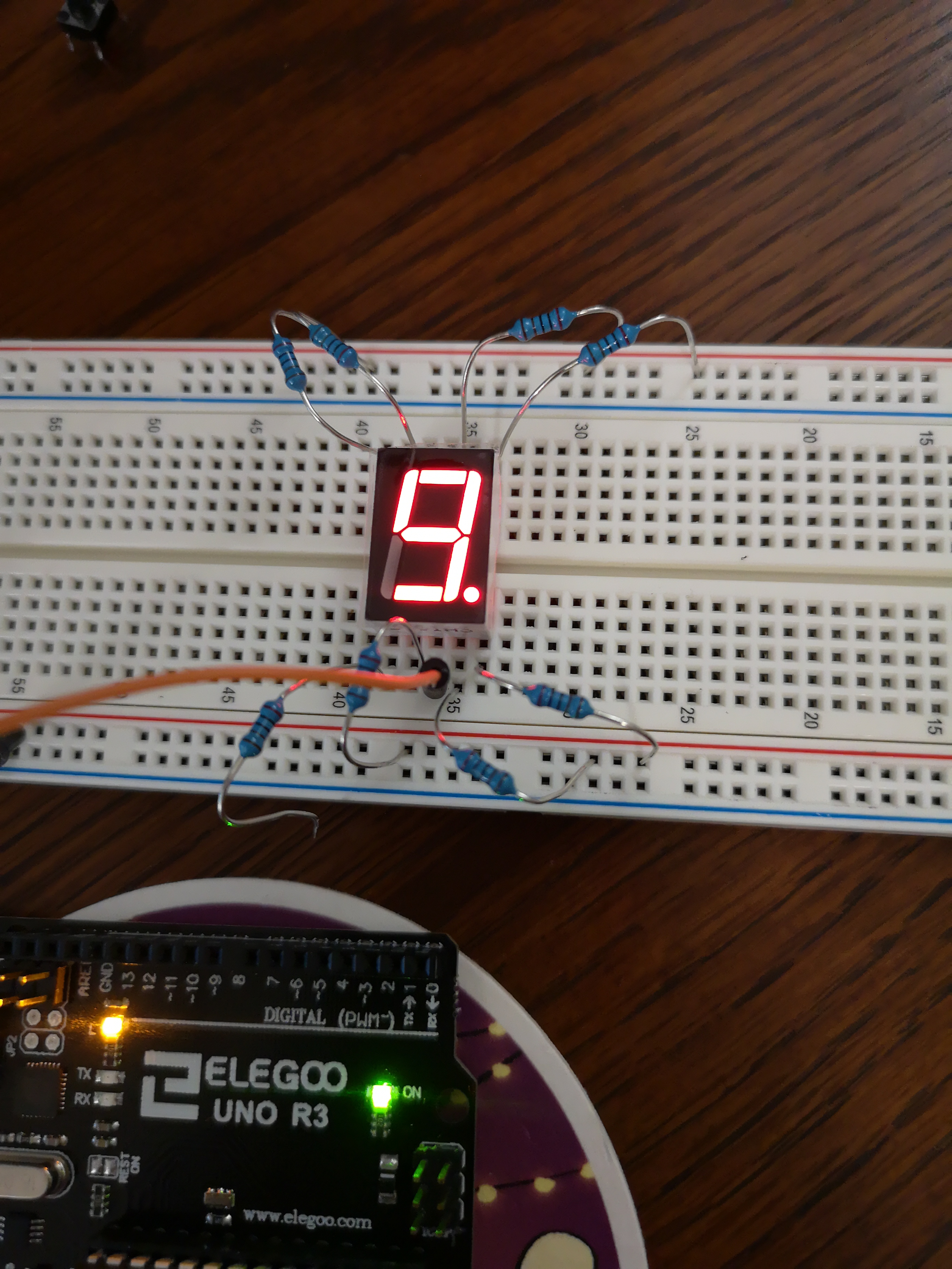
Figure 11. Digits 0-9 are displayed on an SSD using only a 5v connection and manually connecting wires.
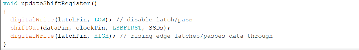
TASK 2.3
Using
the 74HC595N shift register we are able to power the SSD using only one
wire from the arduino to control all seven pins.
Part 1
Figure 12. A video showing the shift register used to power a series of LEDs
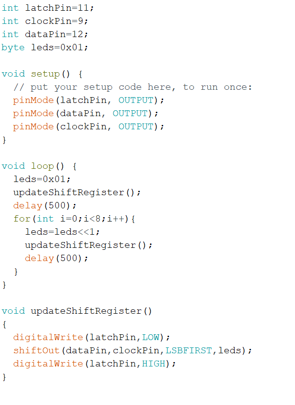
Figure 13. The code used by the Arduino to transmit the data to the shift register.
Part 2
This can then be applied to the SSD
Figure 14. The shift register is being used to display a series of digits on the SSD
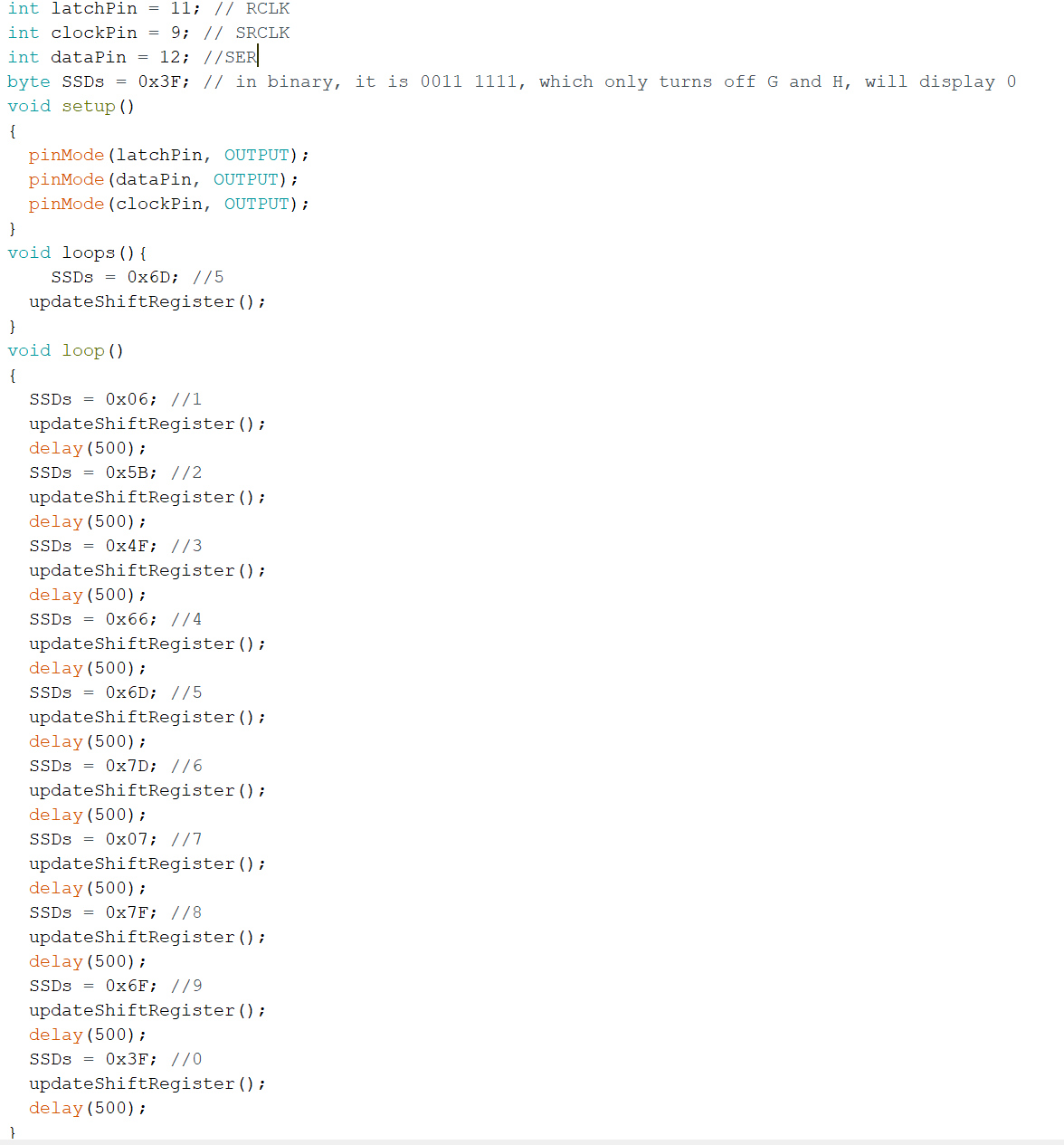
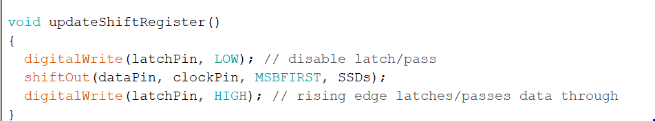
Figure 15. The code used to send each digit to the shift register
Part 3
Figure 16. The shift register being used to display digits on the SSD using a least significant bit first method
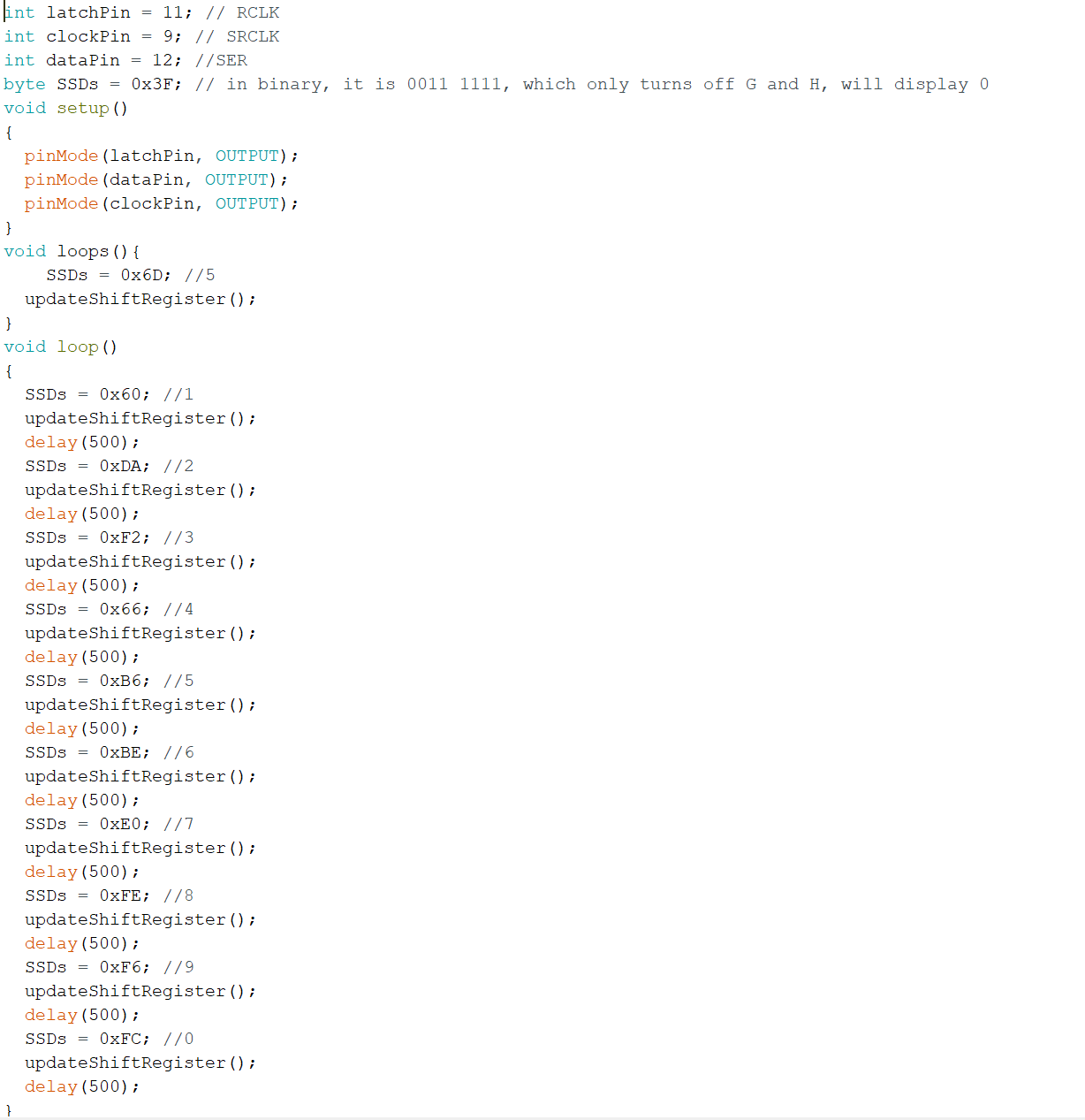
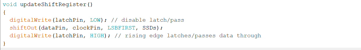
Figure 17. The code used to send each digit to the shift register
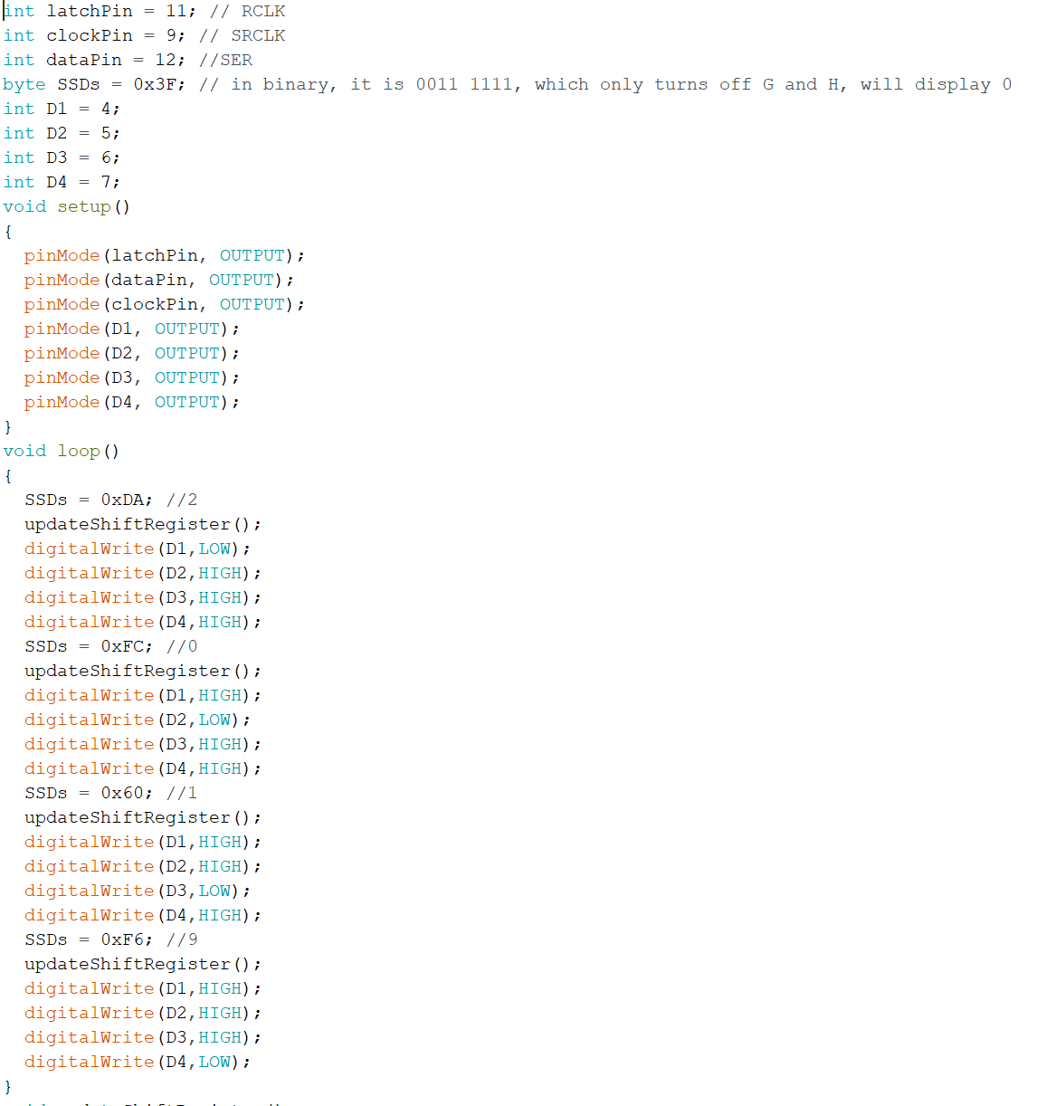
TASK 2.4
Using
a similar technique from the previous task we can display digits on
multiple SSDs. This is done by sending each digit to the shift register
to only one of the four SSDs rapidly. If this is done fast enough it
seamlessly appears as though all four are on at the same time.
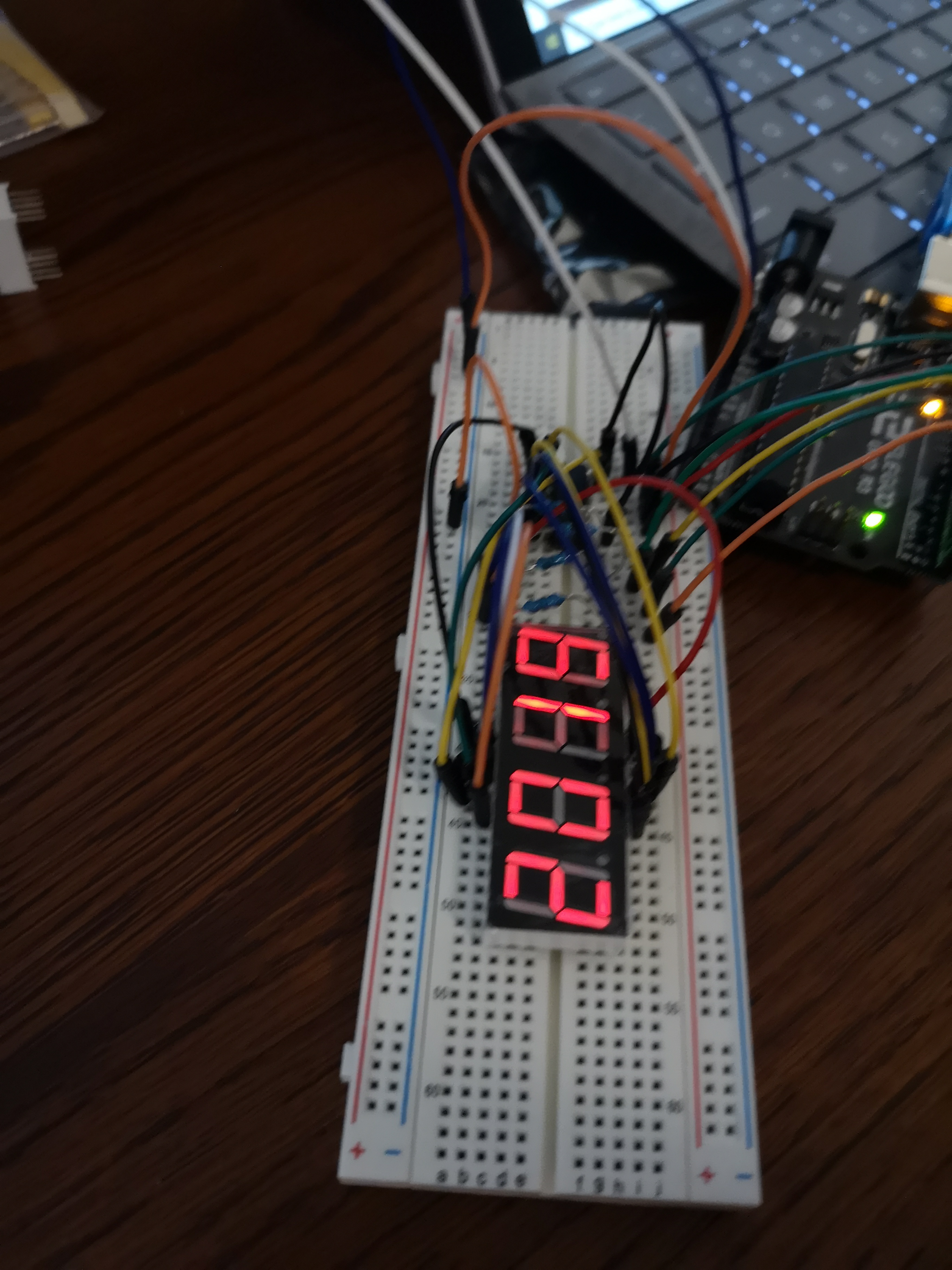
Figure 18. The SSD array displaying the number "2019"