ENGR338 Lab 2021 Fall
Lab 8
Name: David Lee
Email:
djlee1@fortlewis.edu
Design a MUXm and a High Speed Full Adder
Introduction:
In
this lab we used ElectricVLSI to build an 8-bit MUX and an 8-bit High Speed Full Adder
Materials and Methods:
In this Lab we used the computer program ElectricVLSI to create the
schematics that were then simulated in LTSpice.
Results:
Task 1: Build an 8-bit MUX
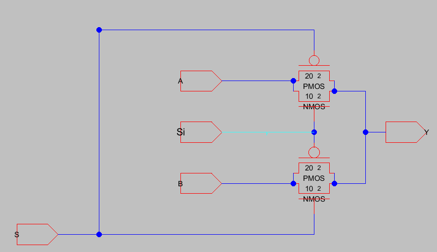
Figure 1: Shows the
Schematic of a MUX
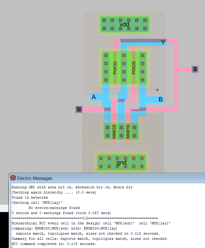
Figure
2: Shows the Layout of the MUX with no DRC or NCC Errors
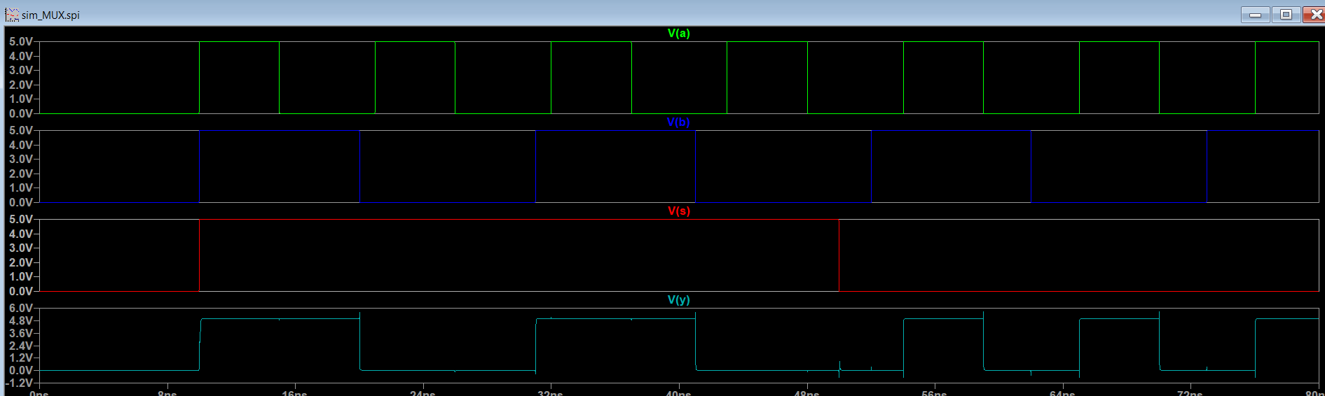
Figure 3: Shows the LTSpice Simulation of the MUX
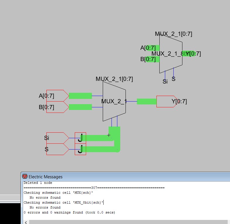
Figure 4: Shows the Schematic of the 8-bit MUX
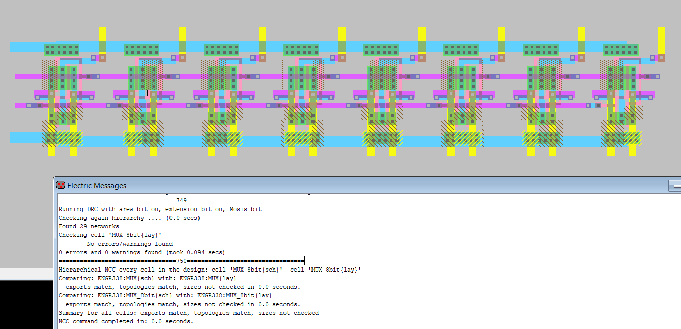
Figure 5: Shows the Layout of the
8-bit MUX with no DRC or NCC errors
Task 2: Build a 1-bit Full Adder
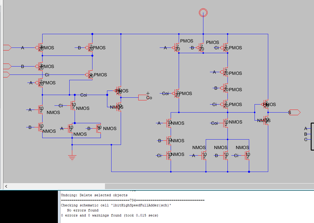
Figure
6: Shows the
schematic of the 1-bit Full Adder
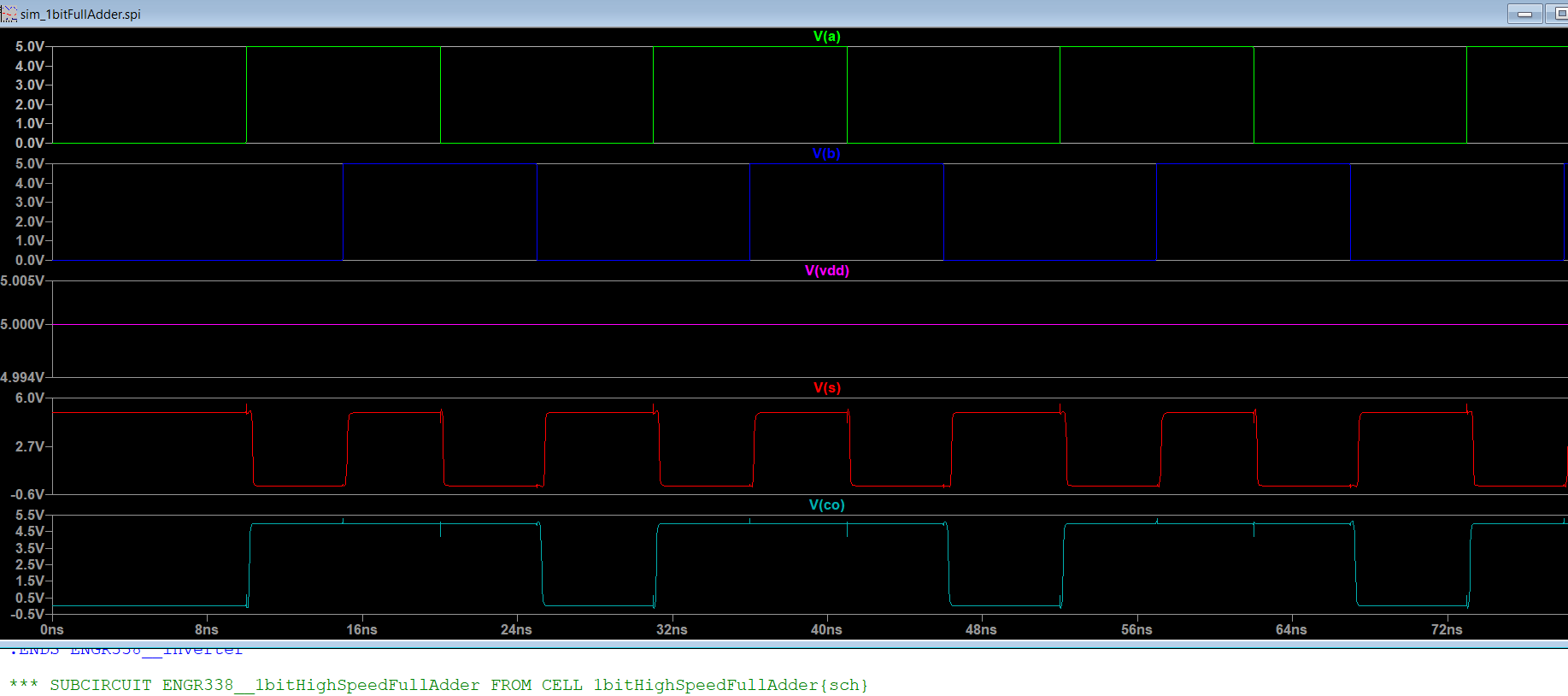
Figure 7: Shows the LTSpice Simulations of
the 1-bit Full Adder
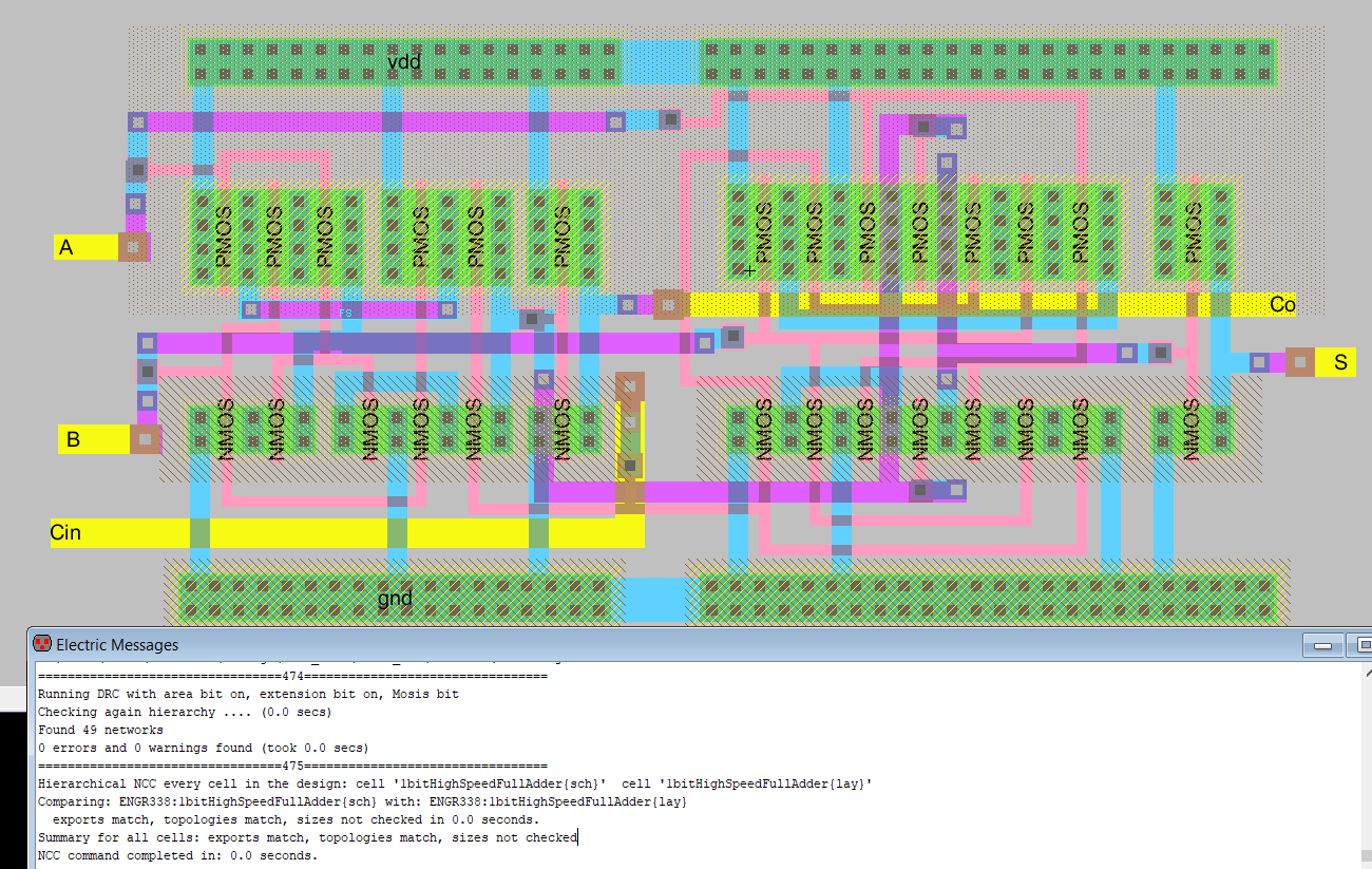
Figure 8: Shows the Layout of the 1-bit Full Adder with no DRC or NCC errors
Task 3: Design an 8-bit High Speed Full Adder
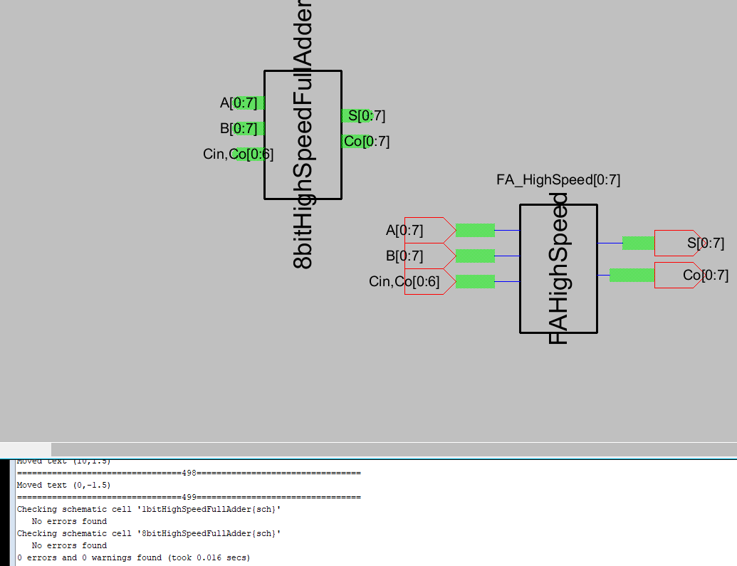
Figure 9: Shows the Schemactic of the 8-bit Full Adder with no errors
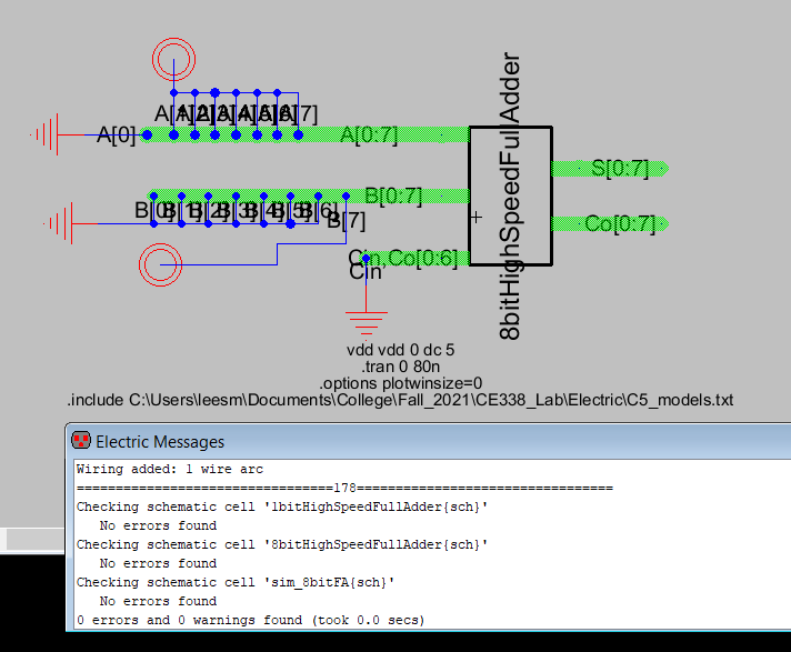
Figure 10: Shows the schematic of the simulation for the 8-bit Full Adder
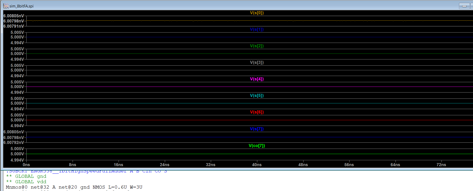
Figure 11: Shows the LTSpice simulation of
the 8-bit Full Adder
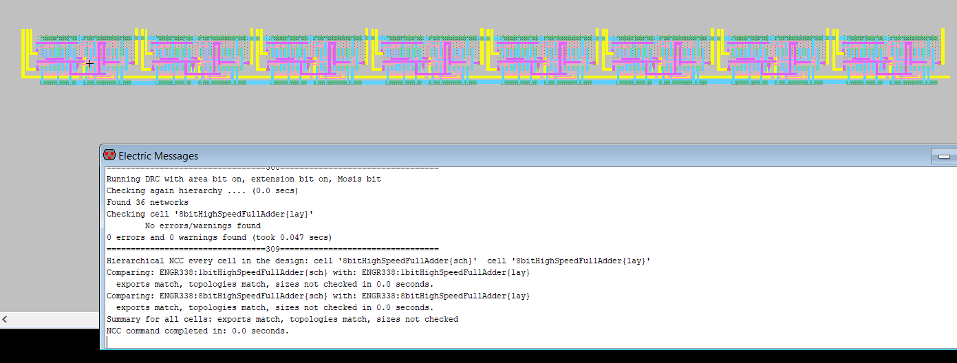
Figure 12: Shows the layout of the 8-bit High Speed Full Adder with no DRC or NCC errors
5. Discussion
The
lab was able to be successfully completed because we were able to
create the simulate and have no errors in the final layout of the 8-bit
MUX and the 8-bit High Speed Full Adder. The biggest problem I ran into
while completing this lab was that while creating the array for the
8-bit MUX the program was creating two copies on top of each other
creating a spacing error. After I was able to figure this problem out
the rest of the lab was able to be completed without to many additional
errors. While creating the 8-bit Full Adder I found that it was easier
to move the C(out) to the same level as the C(in) to be able to connect
them easily in the layout.