ENGR338 Lab 2021 Fall
Lab 5
Name: David Lee
Email:
djlee1@fortlewis.edu
The
Inverter
Introduction:
In
this lab we used ElectricVLSI to build an inverter and then we analysed
the curves in LTSpice.
Materials and Methods:
In this Lab we used the computer program ElectricVLSI to create the
schematics that were then simulated in LTSpice.
Results:
Task 1: Create the schematic of the inverter
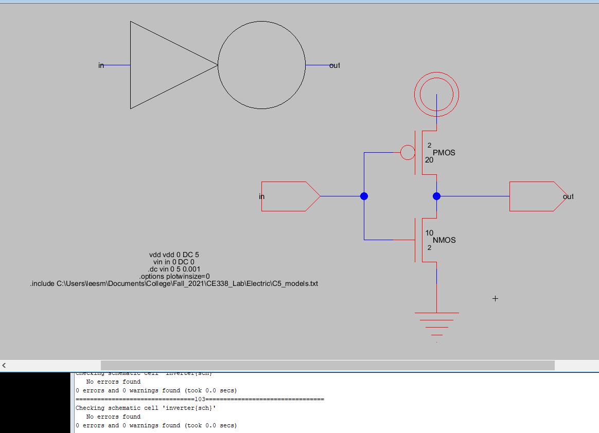
Figure 1: Shows the
Schematic in Electric without an errors present
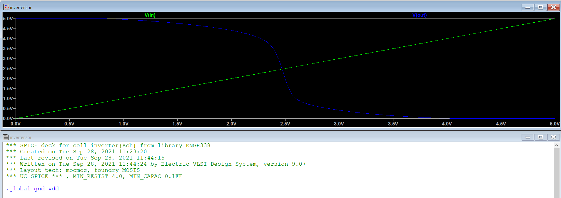
Figure
2: Shows the LTSpice simulations of the inverter
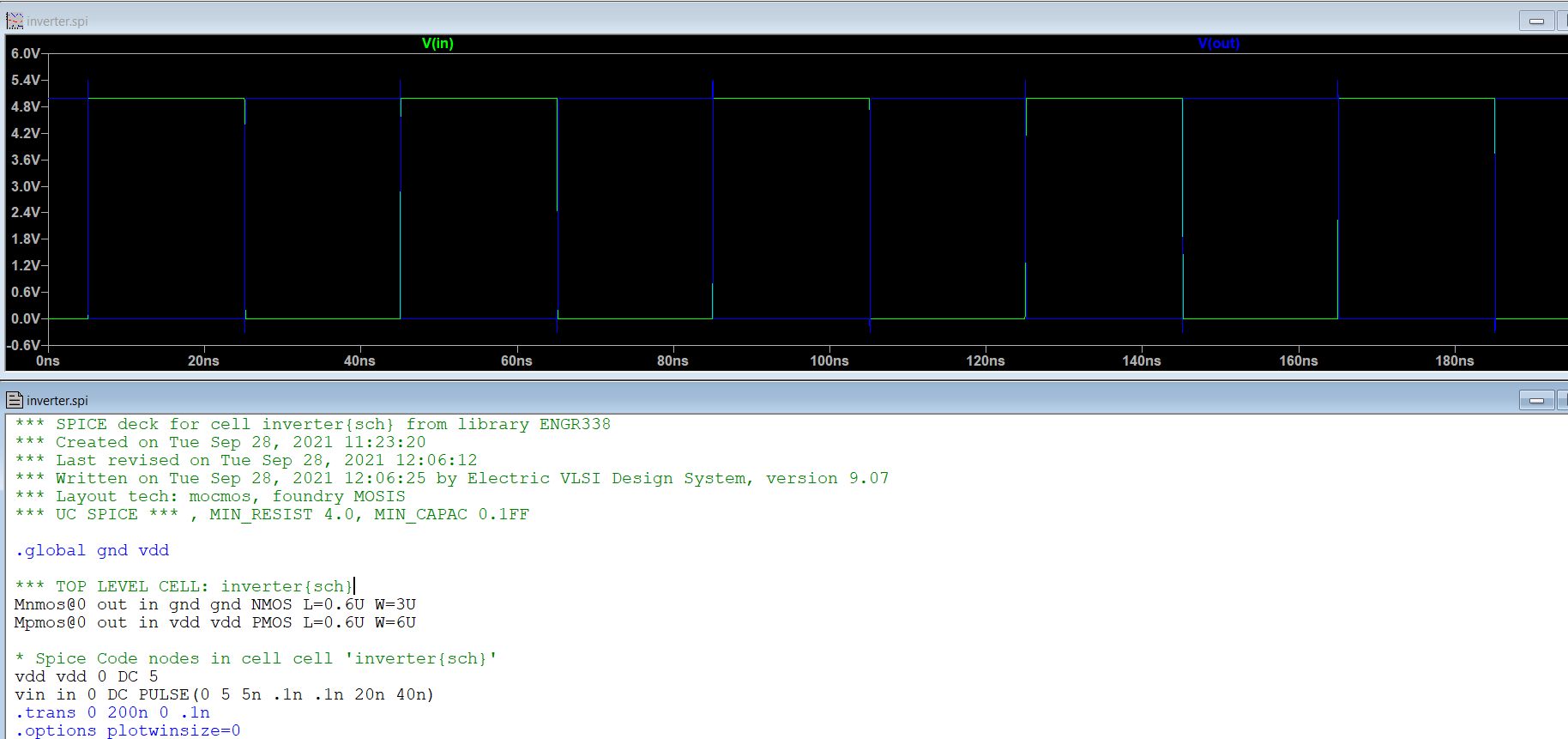
Figure 3: Shows the LTSpice
simulation of the inverter with a pulse input
Task 2: Create the
layout of the inverter
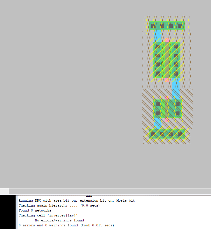
Figure 4: Shows the Layout of the inverter
in an intermediate step without errors
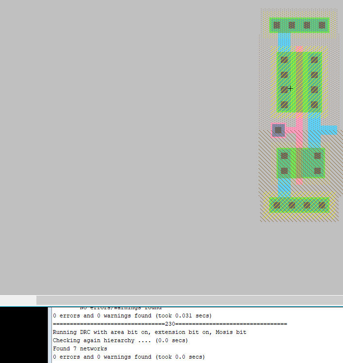
Figure 5: Shows the final layout of
the inverter with no errors after running the DRC
Task 3: Use the
multiplier to build a larger inverter
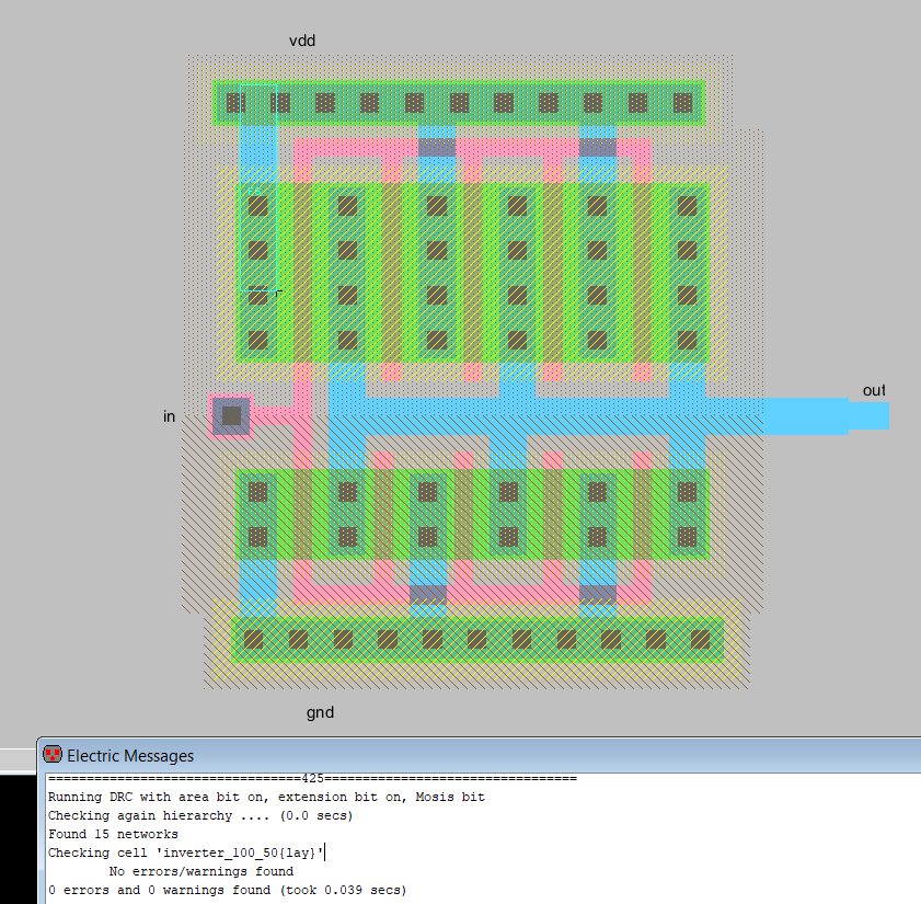
Figure 6:
Shows the layout of the multipler to build a large inverter with no
errors
Task 4: Run
simulations to verify the driving capability of these two different
inverters
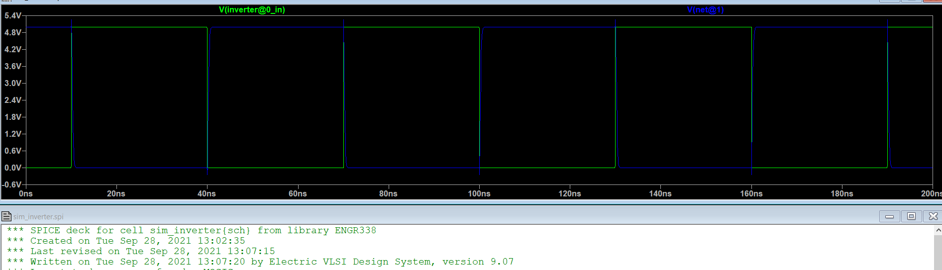
Figure 7: Shows the LTSpice simulation of an
20/10inverter with a 100f capacitor
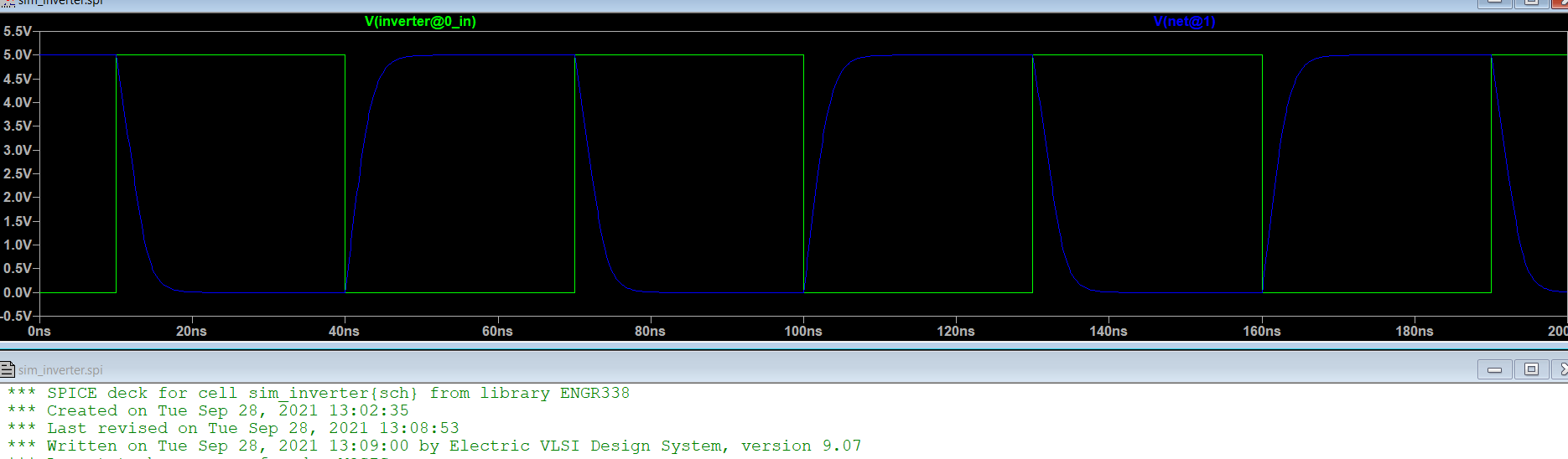
Figure 8: Shows the LTSpice simulation of an
20/10inverter with a 1p capacitor
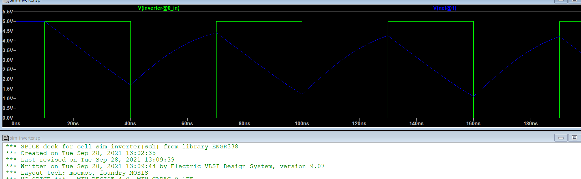
Figure 9: Shows the LTSpice simulation of an
20/10inverter with a 10p capacitor
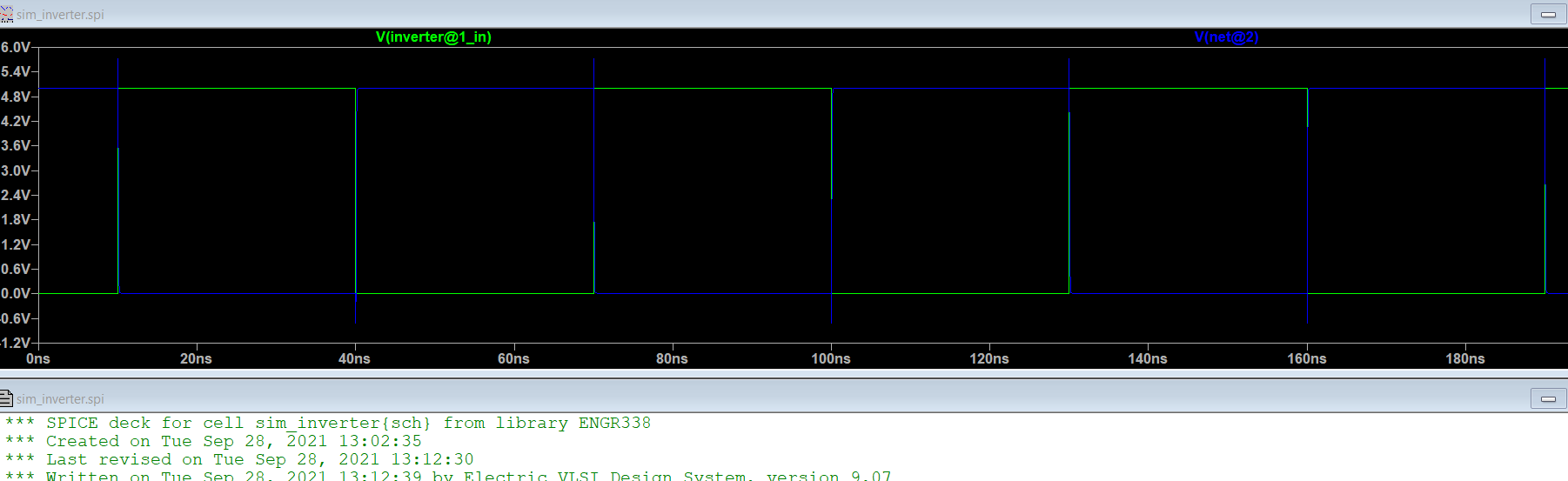
Figure 10: Shows the LTSpice simulation of an
100/50inverter with a 100f capacitor
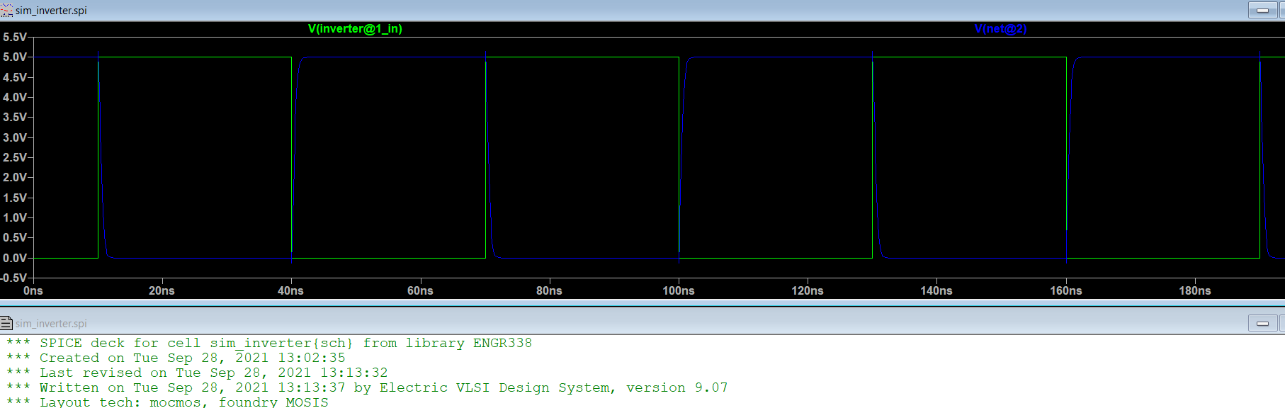
Figure 11: Shows the LTSpice simulation of an
100/50inverter with a 1p capacitor
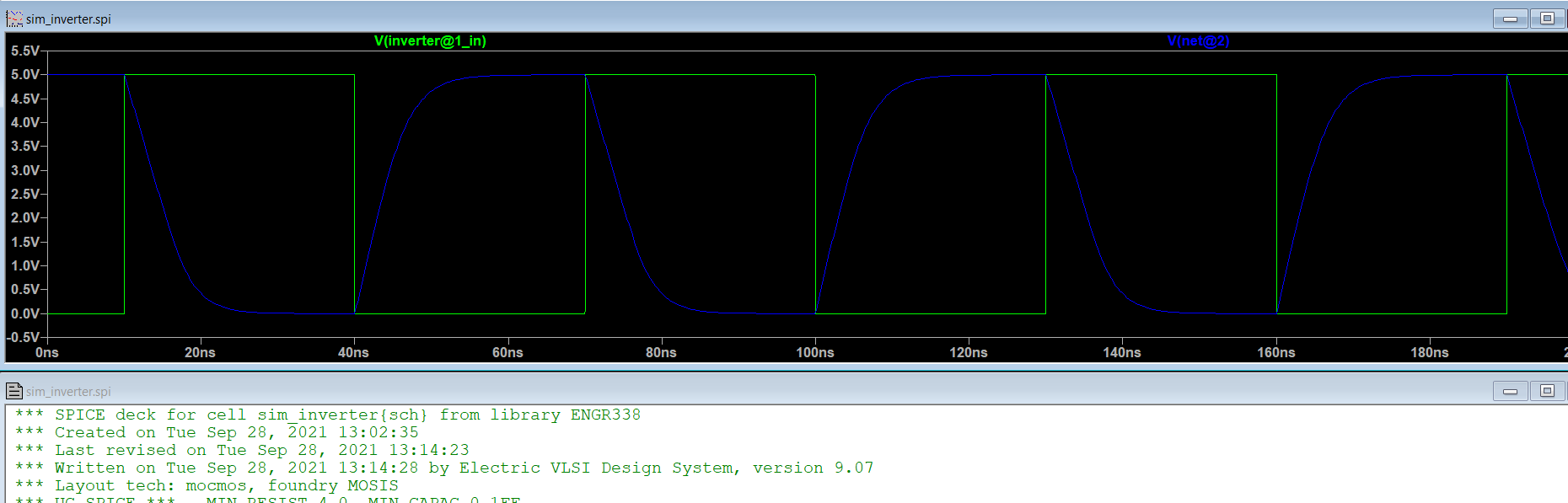
Figure 12: Shows the LTSpice simulation of an
100/50inverter with a 10p capacitor
Task 5: Use a different
simulation tool
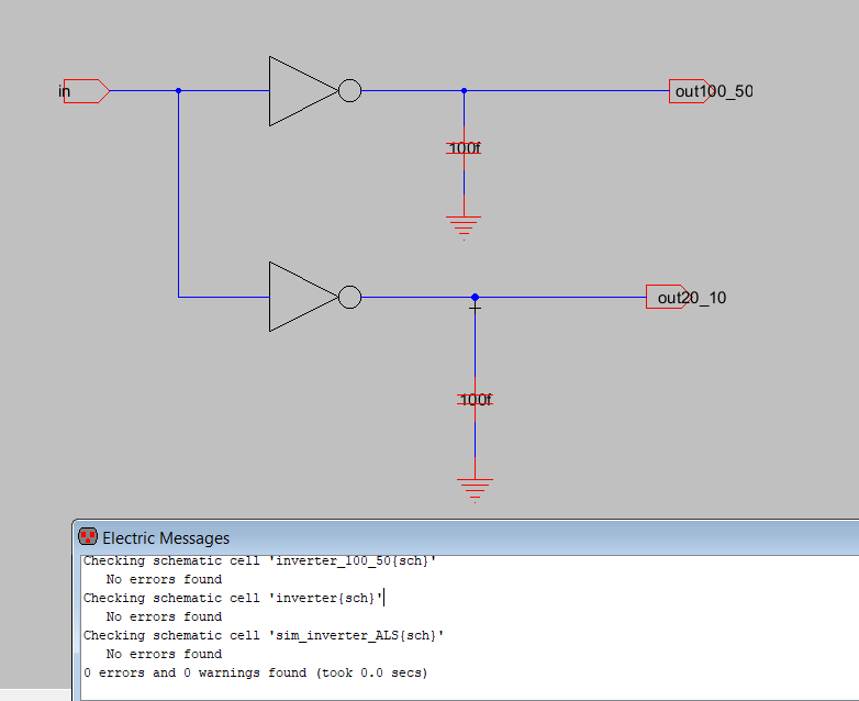
Figure 13: Shows the Schematic of the two
invertors without any errors
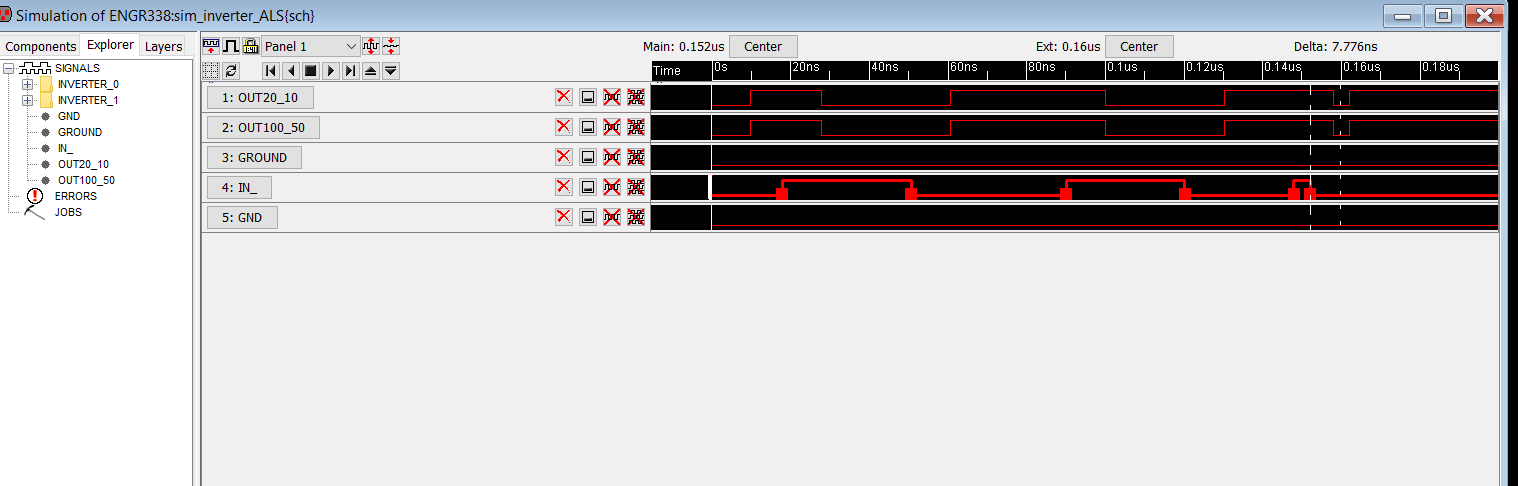
Figure 14: Shows the built in simulation
program in Electric that doesnt show the delay very well
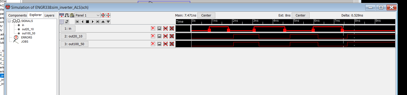
Figure 15: Shows the IRSIM simulation in
Electric that was added to be able to show the delay times better.
5. Discussion
The lab was able to be successfully completed because we were able to
create the inverter and see the inverter work in the LTSpice
simulation. Were also able to use the built in simulation in Electric
to show the delay that the circuit has while be simulated.