ENGR338 Lab 2021 Fall
Lab 3
Name: David Lee
Email:
djlee1@fortlewis.edu
Layout
of an R-2R DAC
Introduction:
In
this lab we used ElectricVLSI to create a layout of a R-2R DAC using
N-Well resistors and test the circuit in LTSpice.
Materials and Methods:
In this Lab we used the computer program ElectricVLSI to create the
schematics that were then simulated in LTSpice.
Results:
Task 1: Create the schematic of the subcells for the R-2R ladder
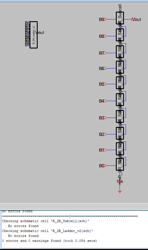
Figure 1: Shows the
Layout of the Subcells in the R-2R layout
Task 2: Create the layout of the subcells for the R-2R ladder
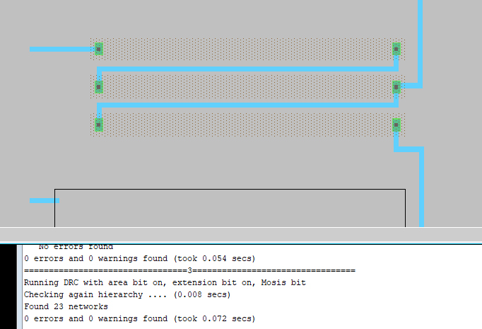
Figure 2: Shows the Cell layout
using the N-Well Resistors with no errors
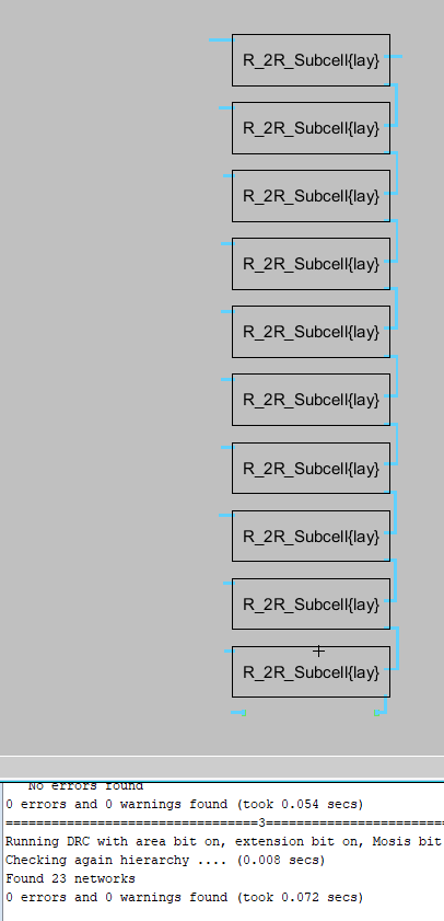
Figure 3: Shows Subcells of the
N-Well resistors with no errors
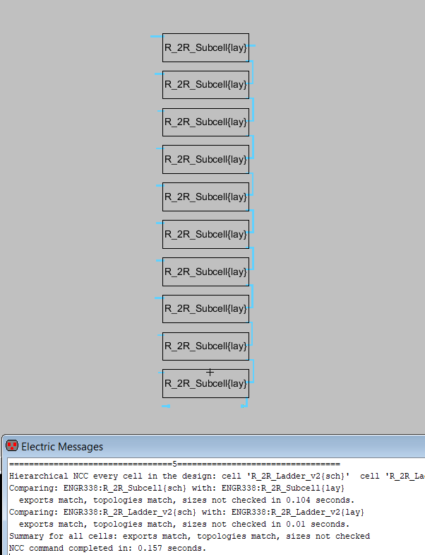
Figure 4: Shows Subcells of the N-Well
resistors with no errors after running NCC
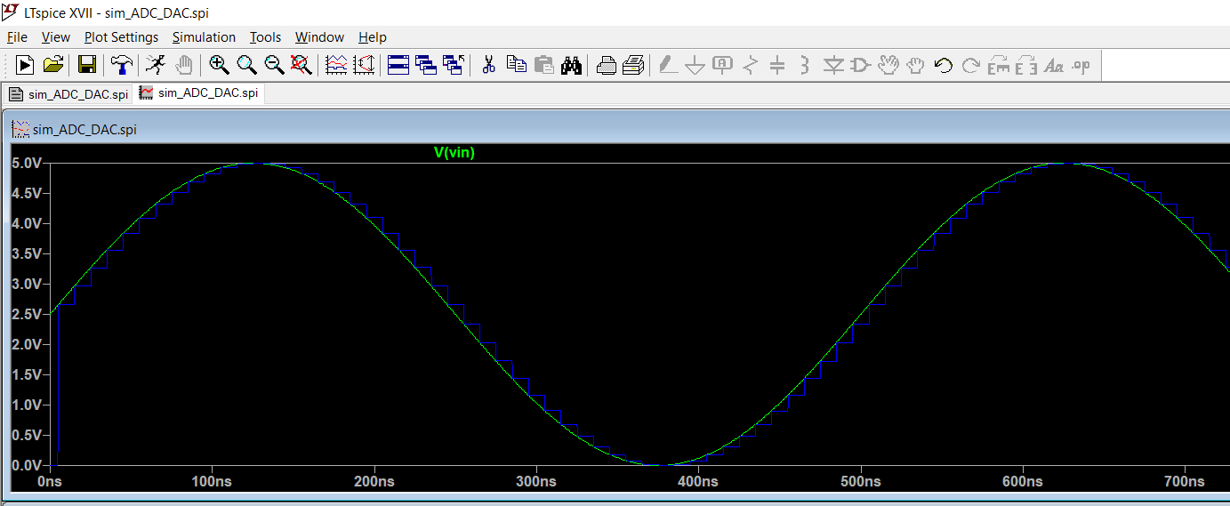
Figure 5: This Figure shows the
simulation results from LTSpice with the R-2R ladder created by using
N-Wells
5. Discussion
The Lab was able to be completed successfully because we were able to
test all the diagrams and layouts without any errors on the multiple
tests that were ran to complete them. The other indicator that the
ladder was created succesfully is the LTSpice output is the output and
similar to what was seen in previous labs.