ENGR338 Lab 2021 Fall
Lab 2
Name: David Lee
Email:
djlee1@fortlewis.edu
Design
of an R-2R DAC
Introduction:
In
this lab we learned how to use the program ElectricVLSI to create and
simulate an R-2R schematic. We designed and our own R-2R Ladder and
created an icon to use in the simulation.
Materials and Methods:
In this Lab we used the computer program ElectricVLSI to create the
schematics that were then simulated in LTSpice.
Results:
Task 1: Copying the Existing ideal ADC-DAC files to your ENGR338
library and run the simulation.
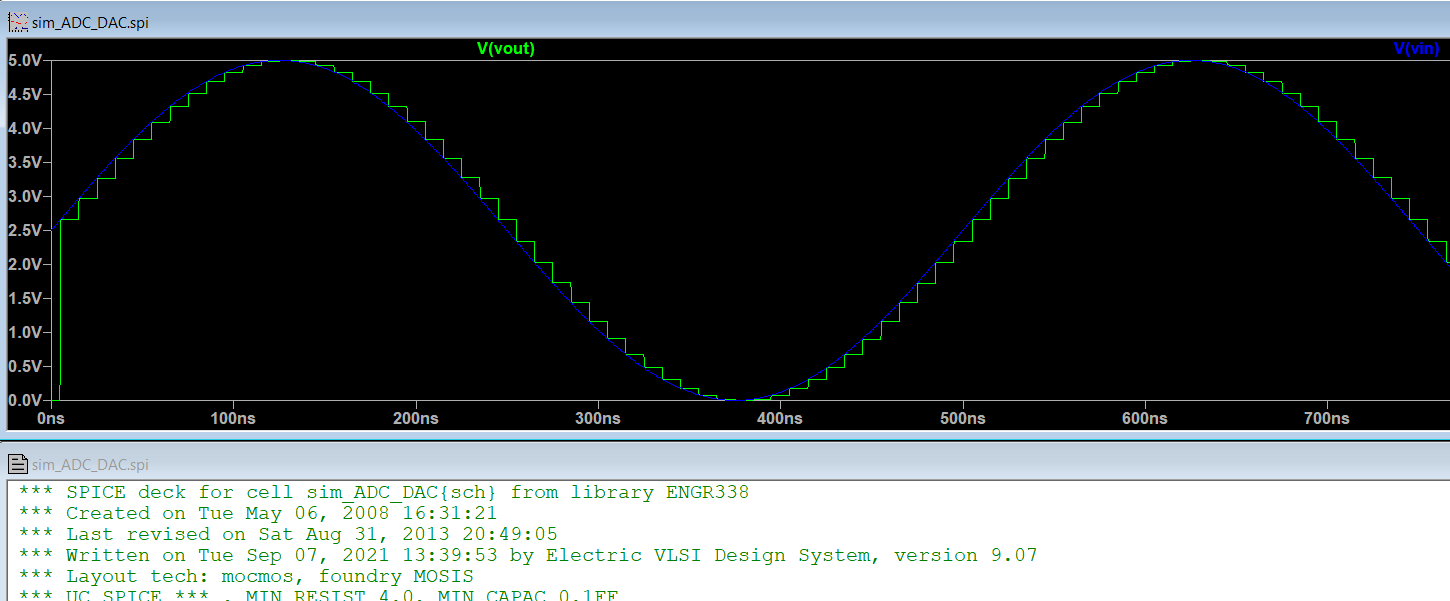
Figure 1: Shows the
simulation results and that the simulation was from the ENGR338, which
can be seen in the first line.
Task 2: Build the schematic of the R-2R DAC and run the simulation.
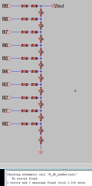
Figure 2: Shows the R-2R
schematic that was created and it contains no errors.
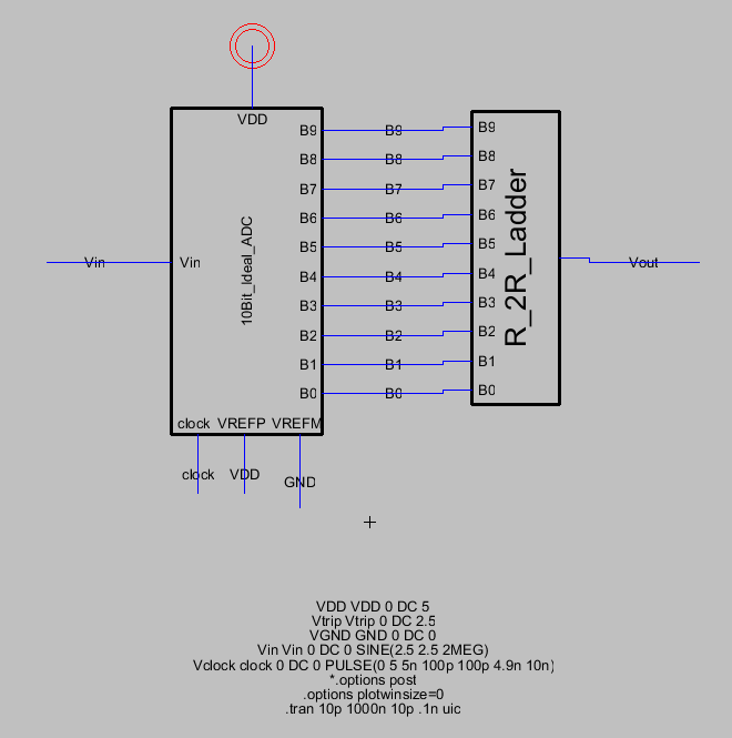
Figure 3: Shows the R-2R ladder
icon in place and connected.
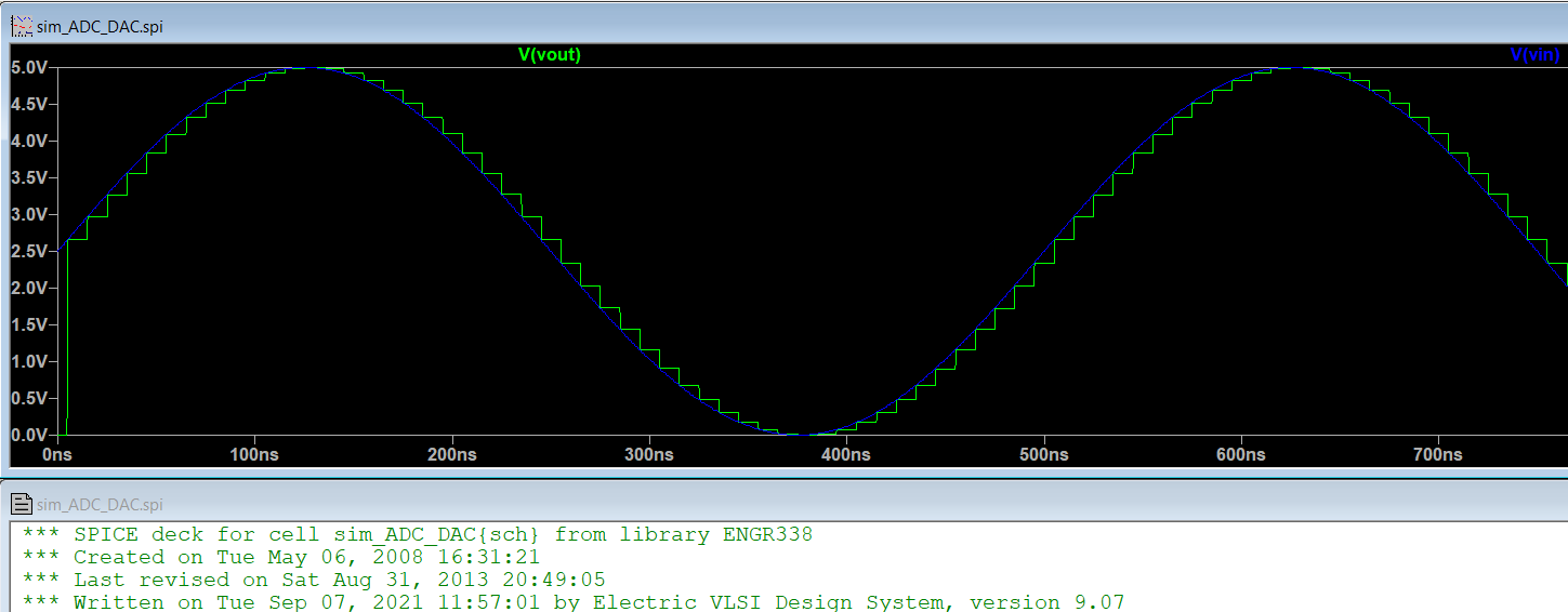
Figure 4: Shows the Simulation
results from the R-2R Ladder
Task 3: Test the
time delay from the B9 pin when the DAC drives a 10pF load.
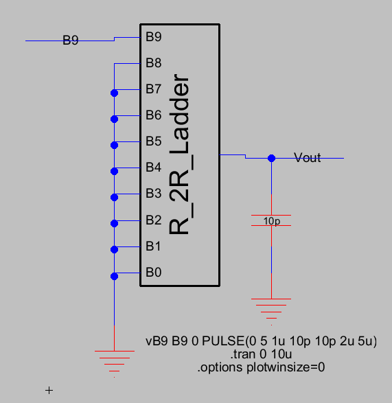
Figure 5: Shows new schematic
of the ladder grounded/ with the load applied
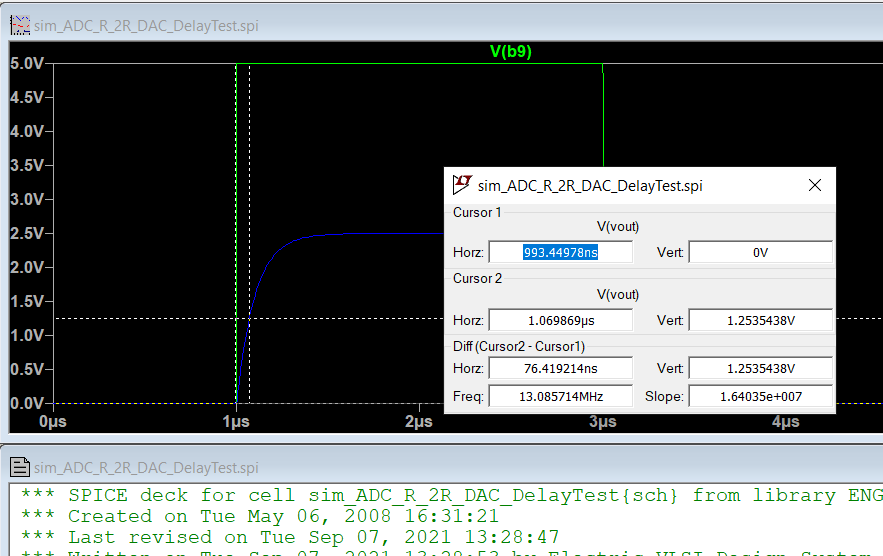
Figure 6: Showing the
simulations time difference with the load applied.
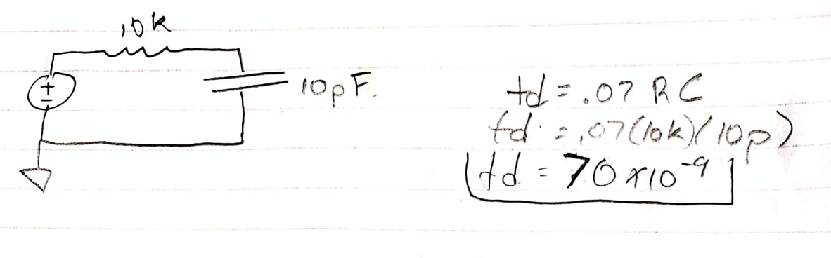
Figure 7: Showing the hand
calculation.
5. Discussion
We are able to compare Figure 1 to Figure 4, to
see that we have successfully created/simulated an R-2R Ladder.
Figure 1 shows the simulation results from the imported files and
Figure 4 show the results from the R-2R ladder that was created in the
lab. Figure 6 shows the horzontal difference for the td = 76ns and the
hand calcuations are approximately 70ns. These comparisons show that
the lab was successful.