2. Introduction: In this lab we learned how to use the UART
protocol with the Basys 3 FPGA board. We learned by implementing a
transmitter and a reciever design in verilog. Along the way throught
these tasks we also implemented a debounce module for the push button,
used
the Arduino Serial Monitor to display transmissions, downloaded and
used a Tera Terminal and practiced ASCII codes.
3. Materials and Methods:
Materials: - Computer
- Basys 3 FPGA Board - Vivado Software
- GVim Software
- Tera Terminal
- Arduino Serial Monitor
Methods:
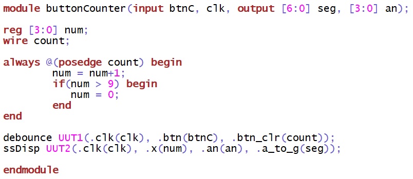
The first tasks was to use the
debounce module code to create a counter and display the counter on the
seven segment display. For this, I used the old ssDisp.v module that
was created from Lab 3. I used a top module that detected the button
push from the debounce module and incremented a variable that was
displayed on the seven segment. For the second task, section two in the
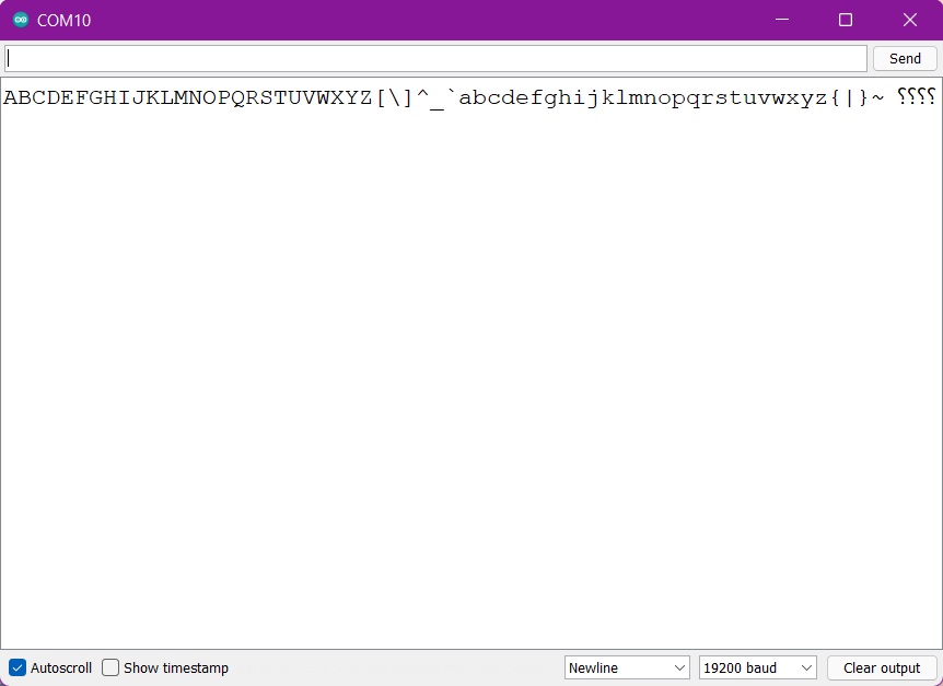
tutorial was followed to make a transmitter. The pushbutton was used
to increment through the ASCII codes starting at 'A', the resulting
letters/symbols can be seen in the serial monitor in Figure 2. For
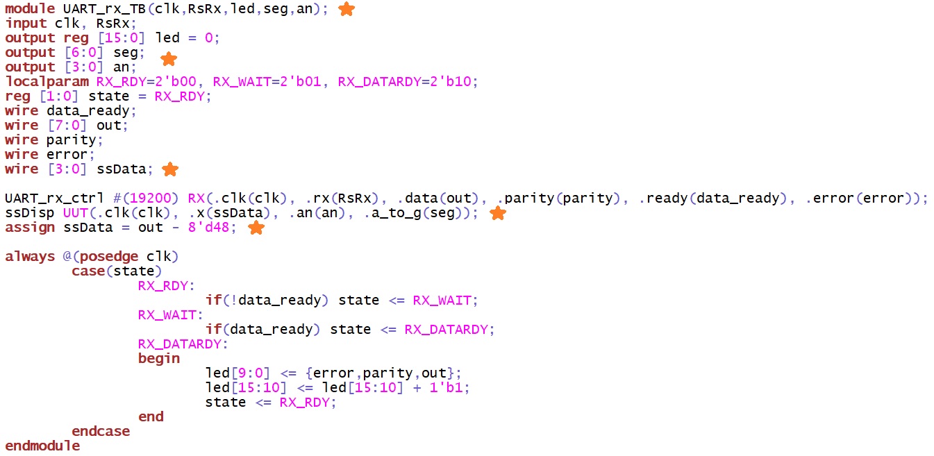
section 3, the tutorial led me through the steps to create a receiver
using the UART protocol. After typing all the given code the module was
synthesized, implemented, and the bitstream was generated. Then the
Tera Terminal was downloaded and the serial port was set up to repeat
the tutorial results; After this was finished the 'ssDisp.v' module was
used again to show the numbers that were typed into the Tera Terminal
in the seven segment display. This last part of the homework was for
Task 4.
Figure 3. Top
code module for receiving code for Tasks 3 and 4. The orange stars show
the code I added for Task 4.
5. Discussion
For this tutorial, the tasks for the turorial went smoothly with very
little issue. I got a little worried when I was getting errors for
numbers 0, 3, 6, and 9 in the last task but then I realized it was
because of the parity check. I combined the results from tasks 3 and 4
because task 3 needed to be done in order to do task 4. Overall a great
and comprehensive tutorial.