CE433 Embedded Systems Lab 8: The Square Problem with Push Buttons and Seven Segment Displays
Name: Audra Benally Email: albenally1@fortlewis.edu
1. Title: The Square Problem with Push Buttons and Seven Segment Displays 2. Introduction: In this lab the FPGA was used with verilog and
vivado to implement a given assembly code.
3. Materials and Methods:
Materials: - Computer - Vivado Software
- GVim Software
- Basys 3 board and cable
- kcpsm.exe application
Methods:
For this lab the FPGA was used
to complete three tasks. The first week instructions were to follow the
instructions and implement tasks 1 and 2. The first task was to simply
follow the directions in section 1. Task 2 was to expand task 1 to
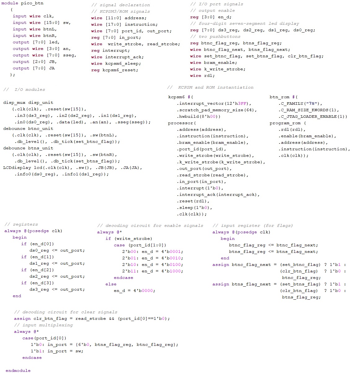
display on the LEDs in binary. Task 3 had challenged us to display the
output in Hex on the LCD display. For this I used the ds0_reg and
ds1_reg wires to send input registers in to the LCD display module that
I used in Lab 7. Then a switch/case is used to assign the data[0] and
data[1] values for display. In theory I'm hoping this will work. I was
not able to test my code.
5. Discussion For
the first task, I had changed the constraint file to match the modules.
This messed me up because in order to remember which button was which
(in case I needed to change it back) I commented on the same lines as
the buttons and had issues with my bitstream for a long time. I could
not figure it out until I got help at the college. Because I had so
much trouble I ended up turning in the first week's work late.
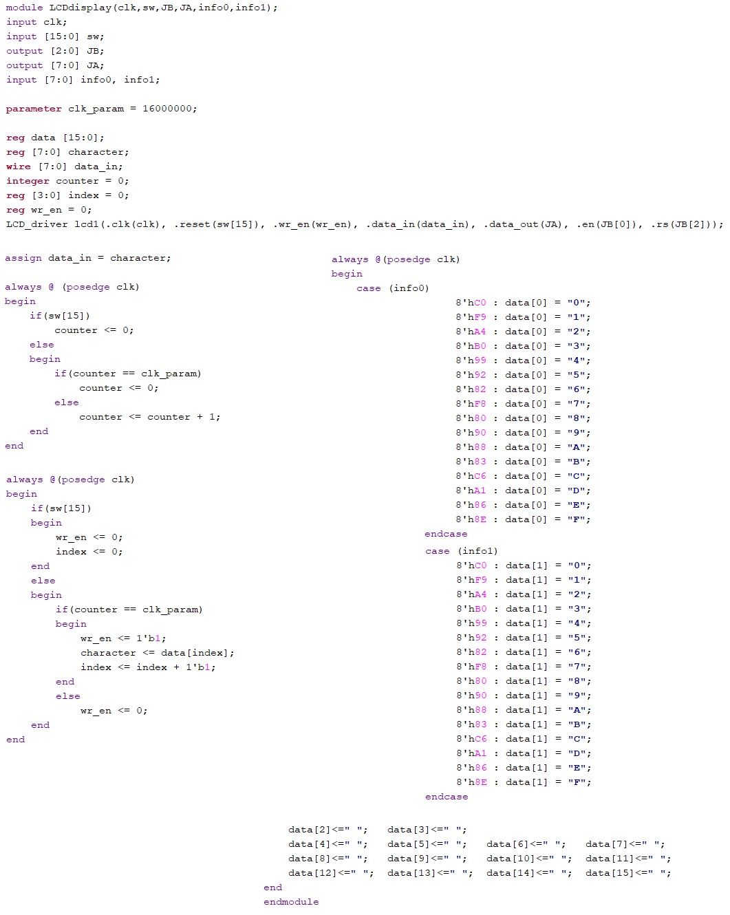
As for the second week, I had trouble getting the
LCD display to work. I don't know what I'm doing wrong. I've rewired
the circuit several times and I've used two differen LCD modules as
well as two different breadboards. I've adjusted the contrast and
tested all the wires as well. I even tried loading the code used in Lab
7 and the LCD display was still blank.. I eventually gave up and just
posted my untested code in Figure 2 above.