CE433 Embedded Systems Lab 6: Basys 3 FPGA to Implement a VGA Driver
Name: Audra Benally Email: albenally1@fortlewis.edu
1. Title: Basys 3 FPGA to Implement a VGA Driver 2. Introduction: In this lab the FPGA was used with verilog and
vivado to alter a 640x480 resolution screen. Static and moving lines
were implemented in the given four tasks.
3. Materials and Methods:
Materials: - Computer - Vivado Software
- GVim Software
- Basys 3 board and cable
- VGA cable
Methods:
For this lab the FPGA was used
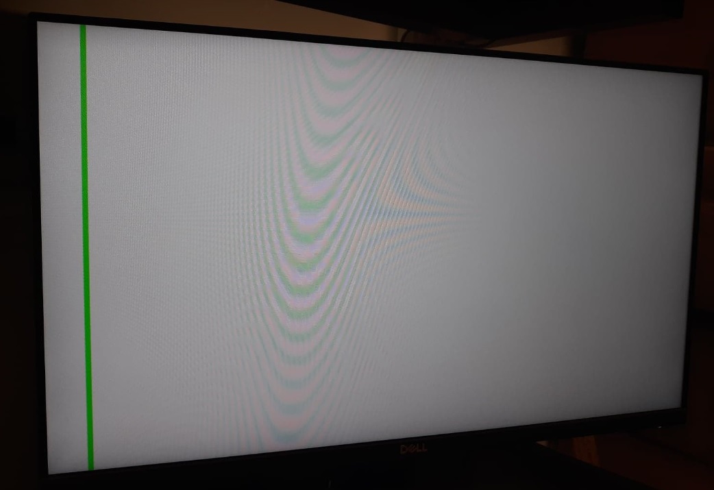
to complete four tasks. For the first task a vertical green line from
horizontal pixels 32 to 35 was implemented. The task was completed by
adding in an if statement that had left and right limits and resulted
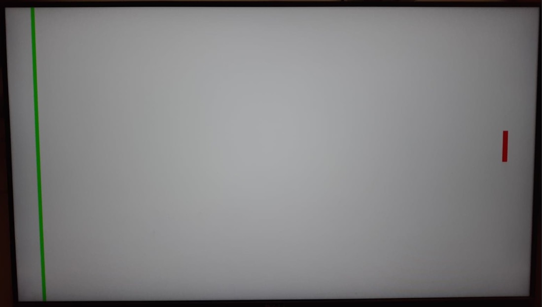
in new color pixel data when triggered. The second task was to
implement a red bar with the boundaries of X: 600 - 605 and Y: 200 -
250. This was also implemented with if statements, this time two if
statements that would trigger when the upper, lower, left, and right
limits were reached. For these tasks, the limits and colors are
implemented in the testbench module. For the third task, the red line
starts on the left side of the screen and moved to the right side at 1
pixel per 0.5s. The "always @(posedge clk)" code was used to change the
left and right limits every 0.5s. For the last task, the code was
altered to change directions with a boolean "direction" bit using if
statements inside the "always @(posedge clk)" block.
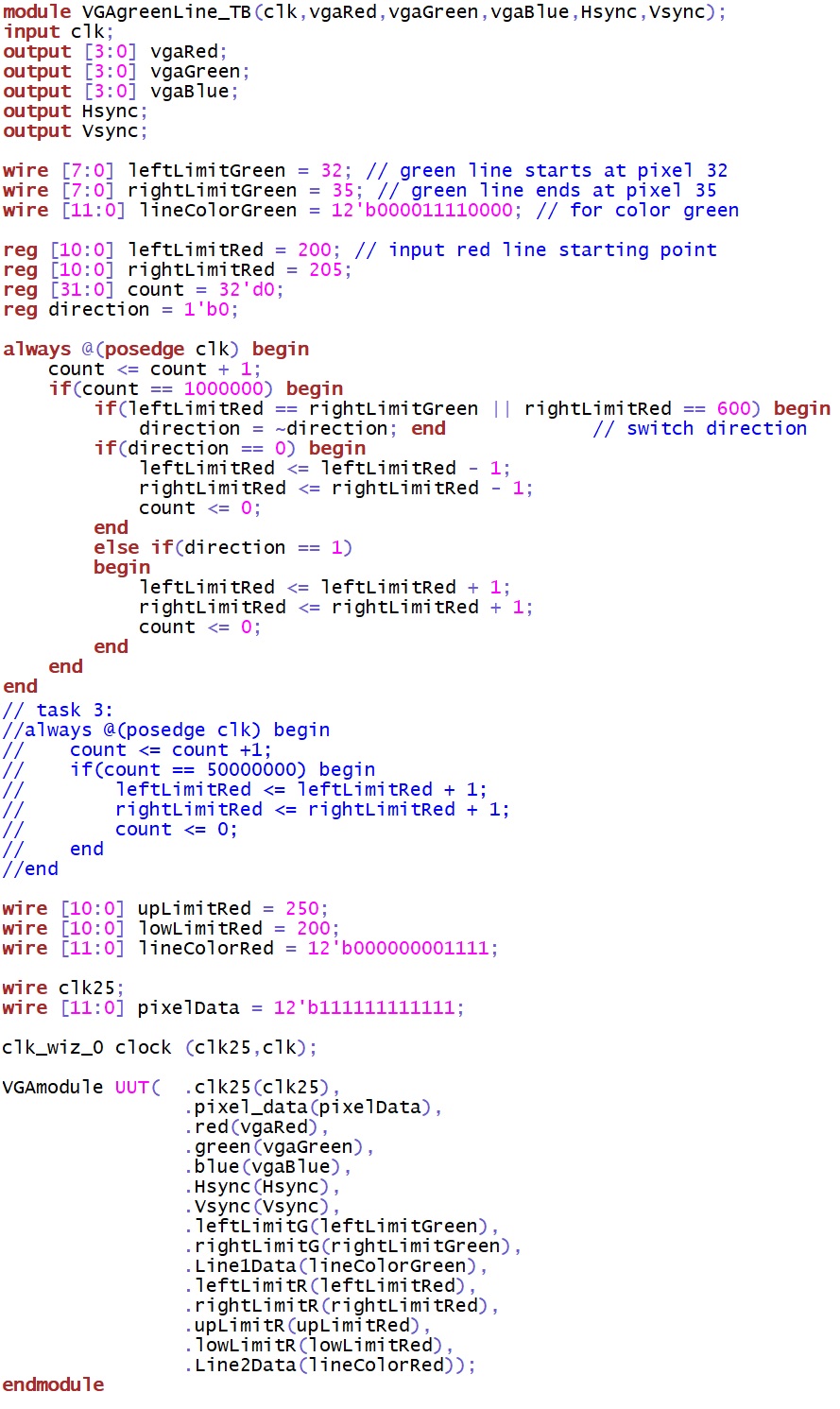
Figure 3. Final VGA module code with segment additions labeled.
Figure 4.
Final VGA testbench code where the line limits, line colors, and line
movement timing is written.
5. Discussion For
this lab I had fixed the glitch that gave me a square screen in the
last homework assignment. The tasks went by smoothly with very little
issue. I enjoyed learning all the little technical implementations
for the VGA modules. For the last task I got a little trouble with the
direction variable but was able to fix it and get the code to work
appropriately.