CE433 Embedded Systems Lab 5: A 3-bit Adder/Subtractor for 2's Complement Signed Binary Numbers
Name: Audra Benally Email: albenally1@fortlewis.edu
1. Title: A 3-bit Adder/Subtractor for 2's Complement Signed Binary Numbers 2. Introduction: In this lab a three bit adder/subtractor was
designed and tested on the Basys 3 board. The module was designed from
the schematic of the adder/subtractor and help from an introduction
video. Then the module was implemented first using the LEDs as outputs
then using the seven segment display on the Basys board as the output.
3. Materials and Methods:
Materials: - Computer - Vivado Software
- GVim Software
- Basys 3 board and cable
Methods:
For this lab the schematic and
information was given about the adder/subtractor. The module was
designed using the schematic connections and an if statement for the
overflow evaluation. For the first step, the inputs and outputs were
connected directly to the Basys 3 board. For the second step, the seven
segment case statements were taken from the seven segment display with
an extra "-" sign used in the case of the [3] output bit. More options
are meant to be added for the seven segment display to be able to
display negative numbers.
4. Results:
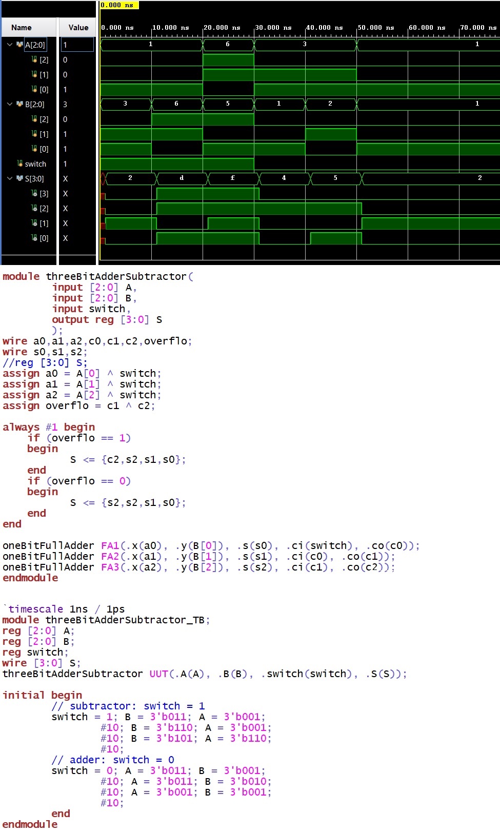
Figure 1.
Three bit adder / subtractor module with simulation to check that the
module is accurate.
Video 1. Step 1 from the lab, Adder/Subtractor is
implemented using the switches as inputs and leds as outputs. Starts
with subtractor.
Video link: https://youtu.be/gNh5EcSPJ2Y
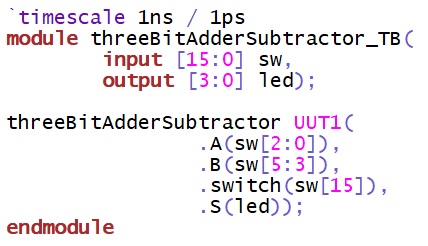
Figure 2.
Connections from the module to the Basys 3 board for step 1.
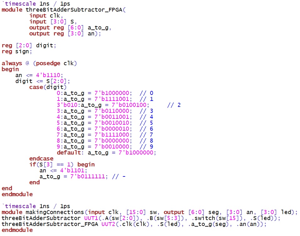
Video 2.
Starting with subtraction, a demonstration of how the code from figure
3.
Video link: https://youtu.be/9yOh-QZsNq0
Figure 3. The
states which I was able to get through. As you can see, I did not
account for all of output possibilities in the code.
5. Discussion This was a fun challenge for the lab. It took me quite awhile to get everything to work at first. I
kept getting turned around with the 2's complement and I thought the
subtractor wasn't working but it was just displaying the non-2's
complement values (so 7 instead of -1) in the simulation.
Then after the adder / subtractor module was successfully simulated the first
step was easy enough to accomplish. The second step gave me some
trouble and I had to get the digits to work before implementing the
negative sign. Once I traced all the connections I was able to
straighten out the module and get it to work a bit better. There's
still definitely some bugs and I wasn't able to get everything to work
out correctly on the subtraction side. I think I would need to add more
options via the display decoder but sadly, once again, I ran out of
time.