CE351 Lab 4 2020 Fall
LCDs and Sensors
Name: Audra Benally
Email: albenally1@fortlewis.edu
1. Introduction
In
this lab, a liquid crystal display was paired with several different
sensors in 7 different tasks. The sensors used were a thermistor, a
DHT11 humidity sensor, a TMP36 temperature sensor, and an IR receiver
sensor. After these tasks were completed, the microcontroller chip was
removed and the "bare bones" microcontroller was programmed to blink a
light then make a portable digital temperature meter.
2. The Code and the Results
1. The LCD:
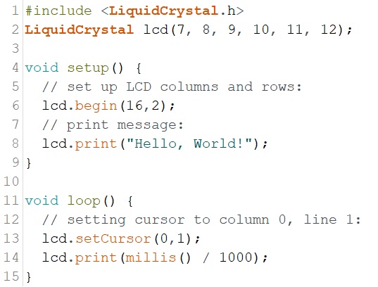
Figure 1.
First circuit code used to print "Hello, World!" and seconds.
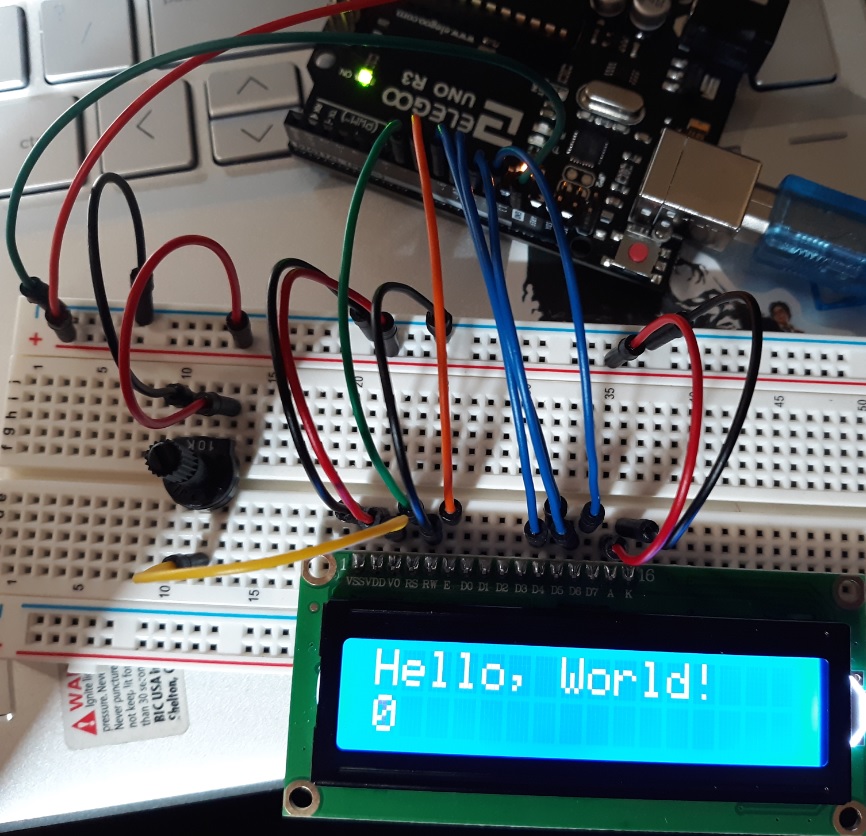
Figure 2. "Hello, World!" printed on the LCD screen.
~~~~~~~ Task 1:
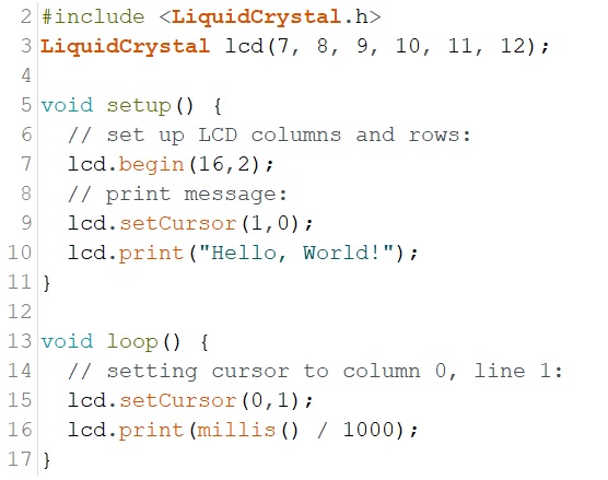
Figure 3. Task
1, the difference is on line 9 where the cursor is set to the second
column, first row.
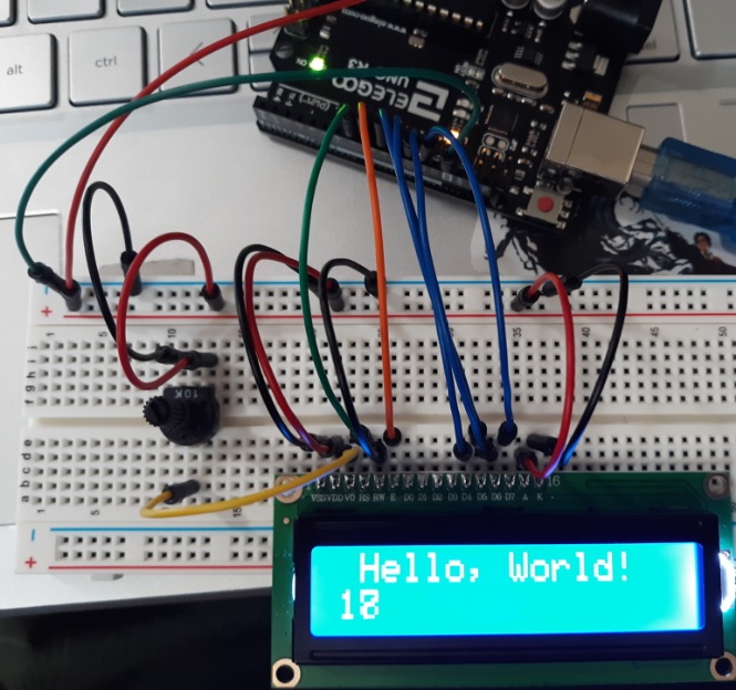
Figure 4. The
resulting LCD screen from the task 1 code.
~~~~~~~ Task 2:
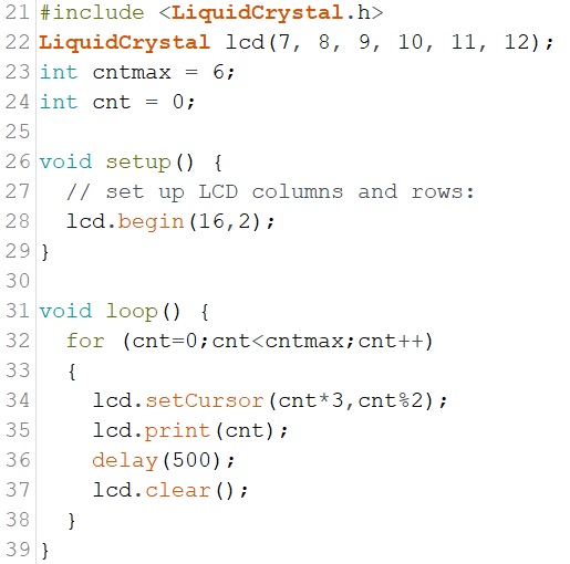
Figure 5. Task 2 code with added flair on line 34.
Link: https://youtu.be/aCb6Q5638CU
Video
1. Task 2 LCD screen result, the video did not go long enough to show
the reset to 0 but the code does make it repeat (void loop).
~~~~~~~ Task 3:
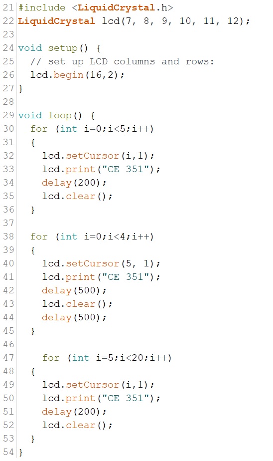
Figure 6. Task 3 code.
Link: https://youtu.be/TGXlwWFhSMs
Video 2: Resulting LCD screen from task 3 code.
~~~~~~~ Task 4:
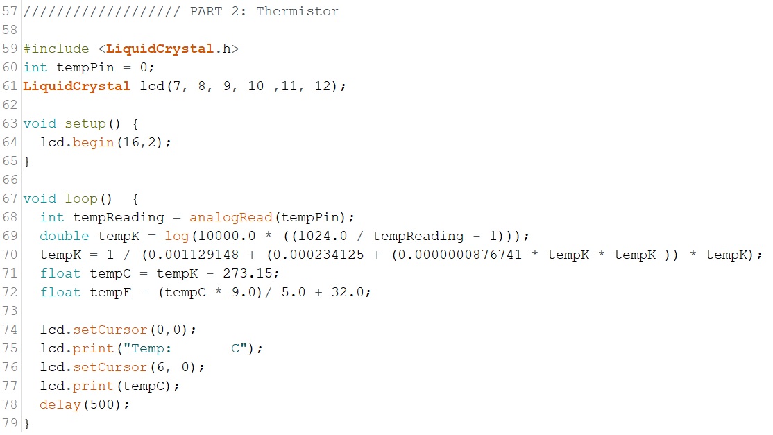
Figure 7. Task 4 code.
Link: https://youtu.be/gXWPflrstSc
Video 3. Resulting LCD screen from task 4 code.
~~~~~~~ Task 5:
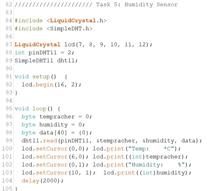
Figure 8. Task 5 code.
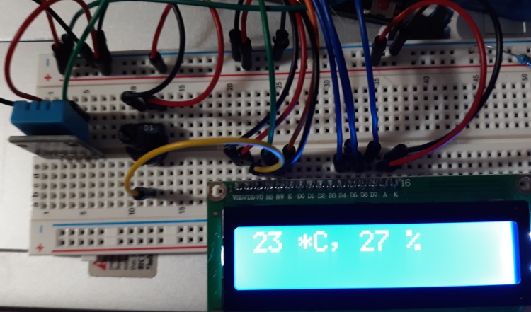
Figure 9. Resulting LCD screen from task 5 example code.
Link: https://youtu.be/epgjx93QxGY
Video 4. Task 4 LCD screen from code from figure 8.
~~~~~~~ Task 6:
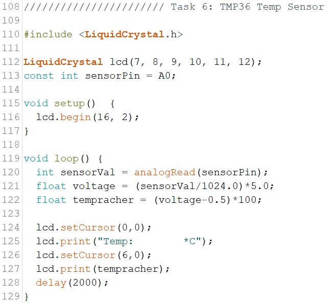
Figure 10. Task 6 code.
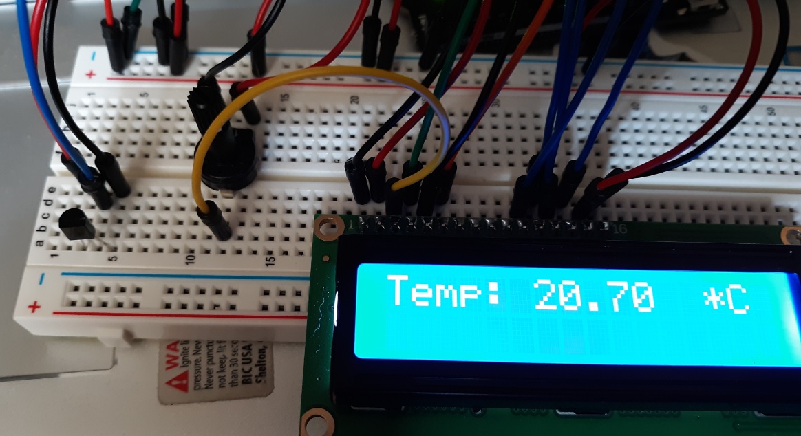
Figure 11.
Resulting LCD screen from task 6 code. TMP36 sensor is also connected
on the left.
~~~~~~~ Task 7:
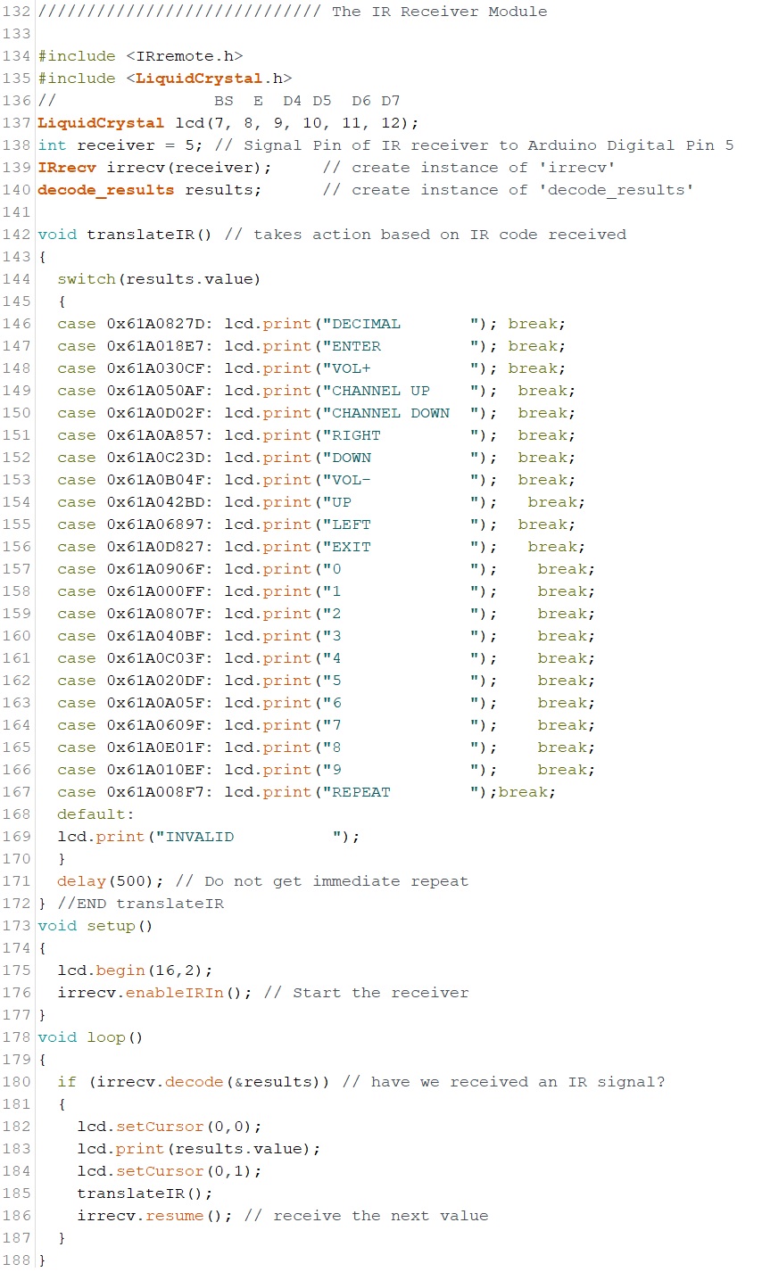
Figure 12.
Task 7 code with switch cases changed for the following remote control.
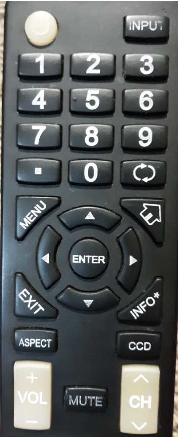
Figure 13. My
own remote used for task because I did not grab the given remote.
Link: https://youtu.be/IVprw8mMDgI
Video 5.
Video taken pressing all the buttons that were mapped in the code from
figure 12.
~~~~~~~ Task 8: Bare Bones
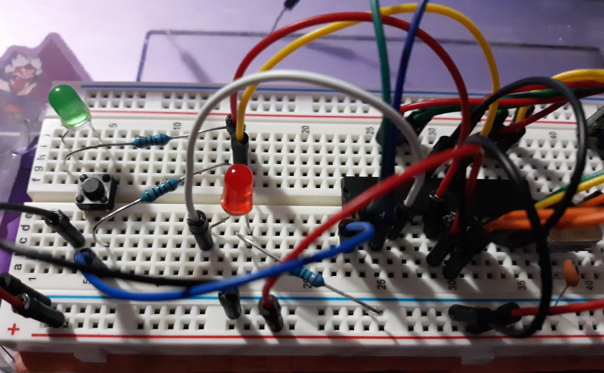
Figure 14. Bare bones circuit set up.
Link: https://youtu.be/UWkfdQUzQYU
Video 6. Code and blinking led from the bare bones set up.
~~~~~~~ Task 9: Portable Thermometer
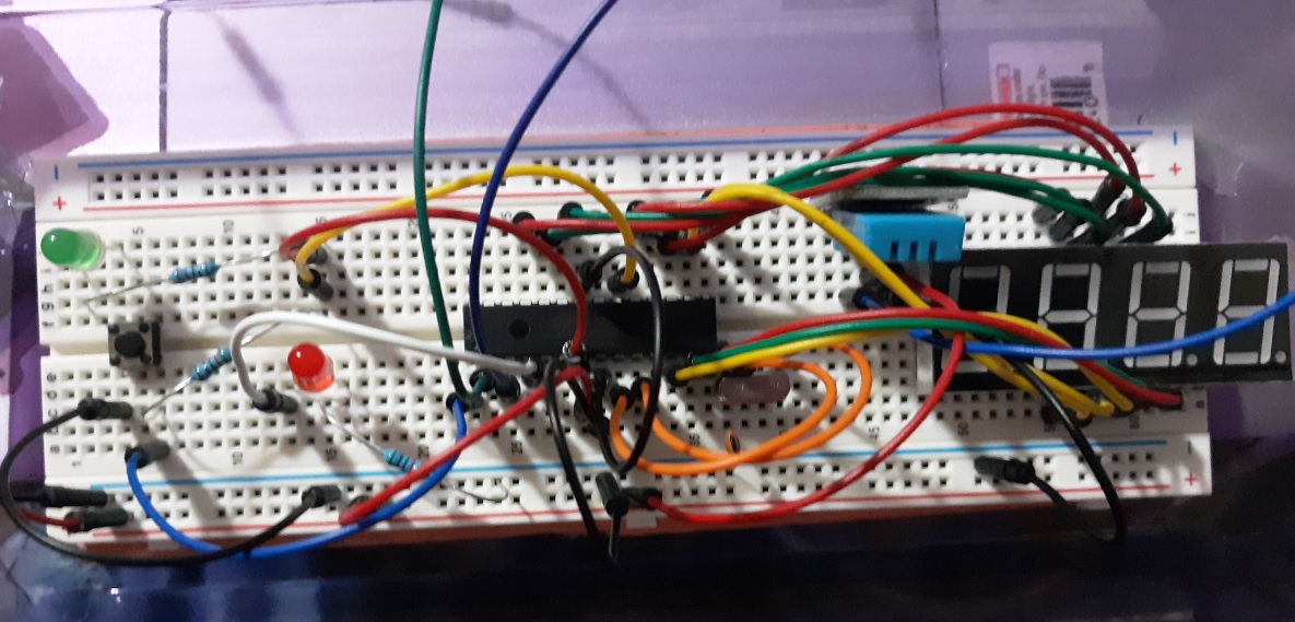
Figure 15.
Full Circuit (including blink circuit) with one missing capacitor by
the orange wires (near oscillator). Before getting capacitor replaced.
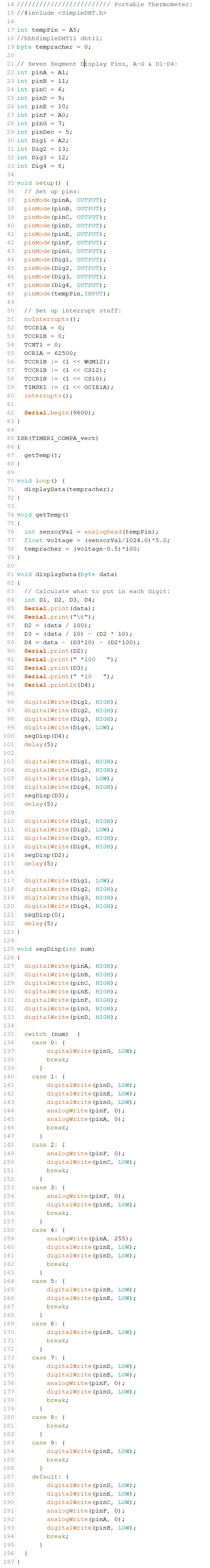
Figure 16.
Task 9 code. I realized too late that I should have used the shift
register to display the digits.
Link: https://youtu.be/aejy1-5j9n0
Video 7. After much tinkering this is what I was able to do.
Discussion:
Learning about LCS screens and sensors in this lab
was very informational. The LCD screen coding was easy to understand
and learn. The IR sensor was really fun to play with and I enjoyed
mapping an unknown remote control. The bare bones circuit was tricky,
especially with all the issues. I was able to get the LED blink to work
but the thermometer was giving me problems. In my debugging I switched
out the temperature sensors which is why it is different in Figures 15
and 16. I was unable to get the A and F segments to work; I tested the
seven segment display in another circuit then I tried switching to
analogRead(), then I switched out the wires. I'm not sure what the
problem was but maybe it had something to do with those being the only
analog pins used? Overall, awesome lab!!