CE433 Embedded Systems Lab 3: Seven-Segment Display on an FPGA
Name: Audra Benally Email: albenally1@fortlewis.edu
1. Title: More about FPGA - Seven Segment Display and Others 2. Introduction: In this lab, we had four separate tasks that
covered combinational logic, the on-board oscillator and the seven
segment display. The tutorial challenged us to create testbenches and
to fill in the blanks for the module verilog code.
3. Materials and Methods:
Materials: - Computer - Vivado Software
- GVim Software
- Basys 3 Board
Methods:
For this lab, the first step was
to create the module code for the combinational logic. These blocks
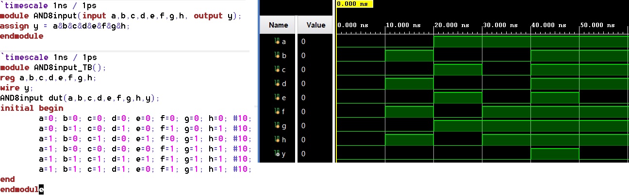
were the inverter, the 2-bit full adder, the 8-input and gate and the
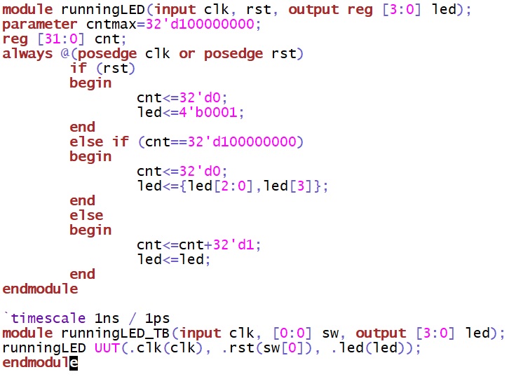
4-1 MUX. The next step was to implement the clk port to make four LEDs
blink for 1 second each. This task also called for a reset switch using
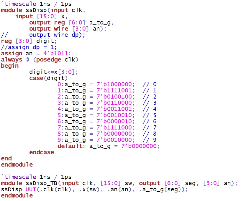
switch 0. The third task involved coding and programming the
seven-segment display. The first three switches were used as the binary
inputs to control the numbering from 0 to 9. For the last task, three
of the four seven-segment displays were turned off and the last display
was used to show digits 0-9.
4. Results:
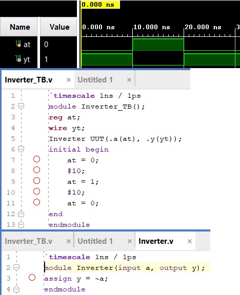
Task 1. Combinational Logic Blocks
Figure 1. Inverter files and simulation results.
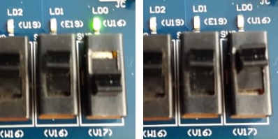
Figure 2. Inverter results on the Basys 3 board.
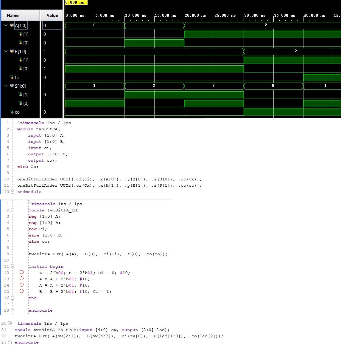
Figure 3. Two bit full adder files & simulation results.
Video 3. Running LED implementation on the Basys board.
Video link: https://youtu.be/3_GMNaih52o
Task 3. Seven-Segment Display
Figure 6.
Seven segment display set up for the next task. For this task the only
difference is the line "assign an = 4'b0".
Video 4. Seven-segment shown on the board.
Video link: https://youtu.be/Nq7Zp5IQJKY
Task 4. Seven-Segment with one Display
Video 5. Seven
segment display with only one display on and the other 3 off.
Video link: https://youtu.be/40k1CqqgYtI
5. Discussion For
this lab, the tutorial was easy to follow and the 'fill in the blank'
style challenges were fun to complete. I enjoyed coding the
seven-segment display and was very excited when it worked for me. The
running LED task was the hardest for me to finish and I had to try a
couple options before getting the code to work. Unfortunately, once
again I ran out of time and did not implement the 4-1 MUX for task 1.
The rest of the tasks were exciting and enjoyable and I feel much more
acquainted with the Basys 3 board.