CE351 Lab 2020 Fall
Power Supply and DC Regulators on a PCB for MCUs
Name: Audra Benally
Email: albenally1@fortlewis.edu
1. Title: Power Supply and DC Regulators on a PCB for MCUs
2. Introduction:
In this lab, a functioning power supply board will
be designed to use with future MCUs. The program being used will be
Eagle PCB. Personal libraries and devices will also be made to
accomodate for parts not included in the SparkFun library. Gerber files
will then be made and sent to PCBWay for fabrication. Once the boards
came in, the components were soldered and assembled. The resulting
board was tested for accuracy.
3. Materials and Methods:
Materials:
- Computer with Eagle PCB
- Step by step tutorials from yilectronics.com
- Calculator
- Soldering iron
- Multimeter
- Flux
- Solder
- Board components: capacitors, inductors, diodes, chips, etc...
Methods:
For this lab, a step by step tutorial was followed
to create a power supply board. The first circuit was constructed with
devices from the SparkFun library. The second and third circuits needed
specific devices that were not included in the given libraries. Several
capacitors, inductors, a diode, and two 5-pin LM2596 devices were
created from the datasheets of each specific component. Once the parts
were built, the last two circuits were constructed. The completed
schematic of the circuit board can be seen in figure 1. The schematic
was then checked for potential errors with an ERC check. Once all the
errors were cleared, the board was constructed and the physical
connections were made. The board was then checked for errors with a DRC
check. Figure 2 shows the completed board layout. Figure 3 shows the
DRC check results. Once the board came in from production, the
components were soldered according to the schematic. The board was then
tested for accuracy; The results can be seen in Figures 6 - 9.
4. Results:
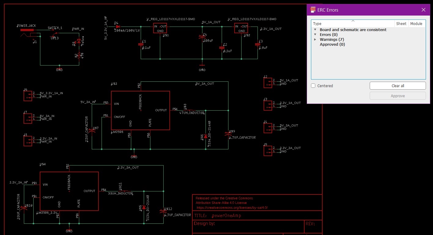
Figure 1. The completed schematic with 0 ERC Errors.
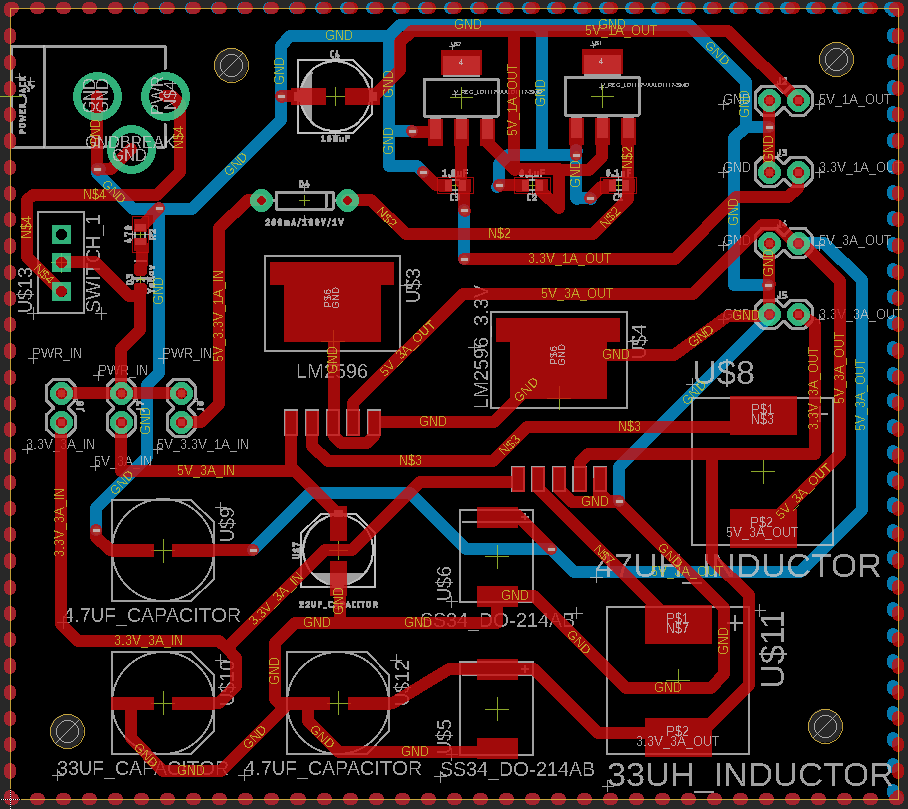
Figure 2. Finished board.
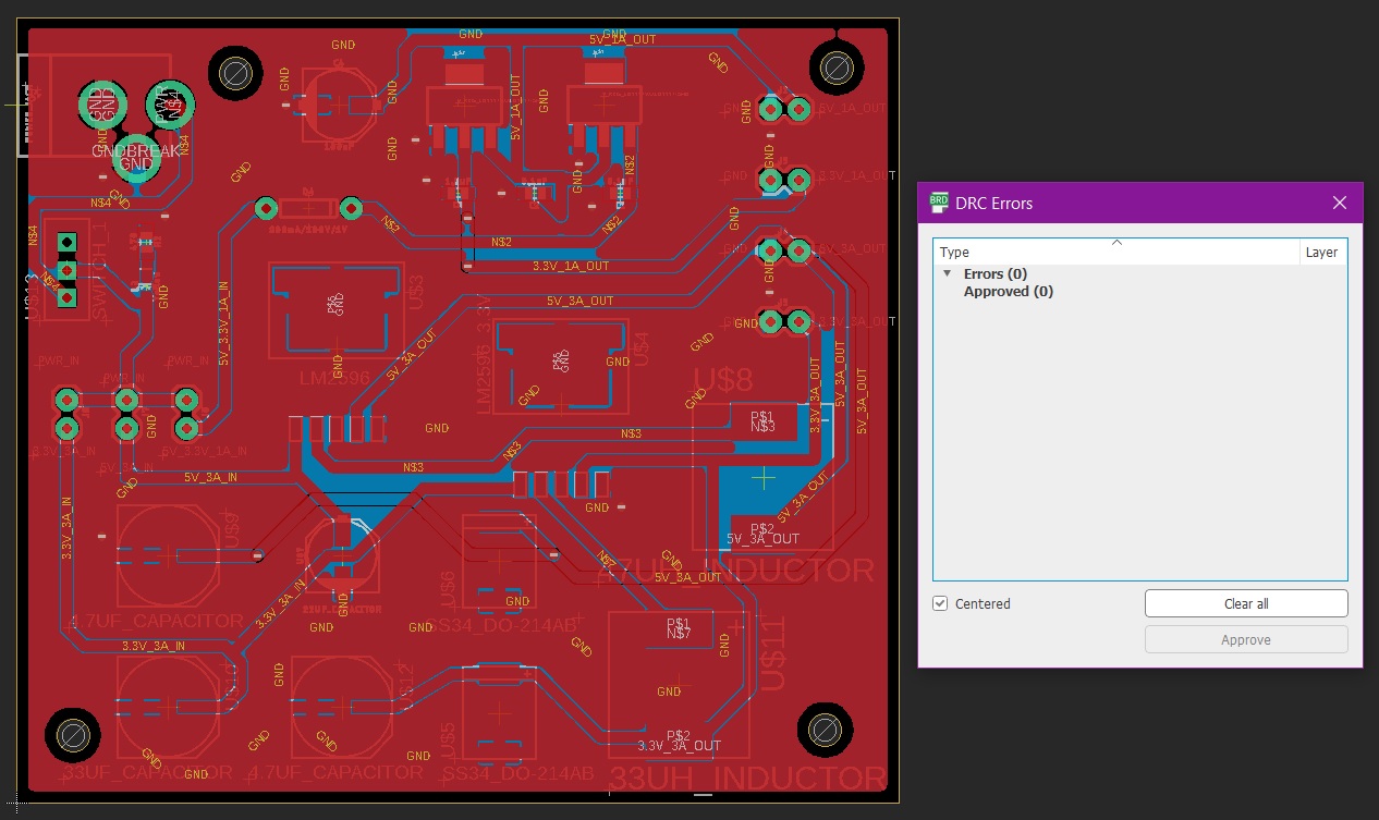
Figure 3. 0 DRC errors in board layout.
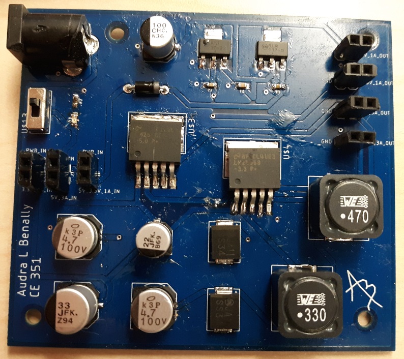
Figure 4. Completed PCB.
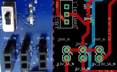
Figure 5. The
power in pins. On the left: 3.3V 3A IN. Middle: 5V 3A IN. Right: 5V
3.3V 1A IN.
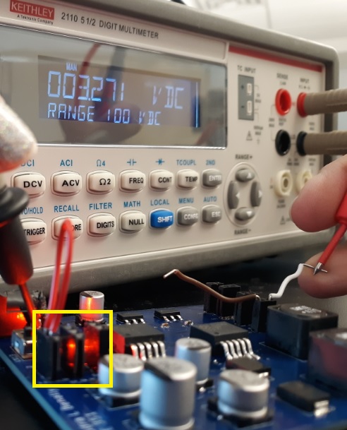
Figure 6. The
far left 3.3V 3A in pin is shorted to the power input and the ouput
shows 3.271V.
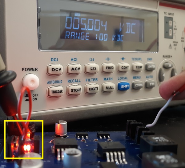
Figure 7. The
middle 5V 3A in pin is connected to power and the ouput correctly reads
5.004V.
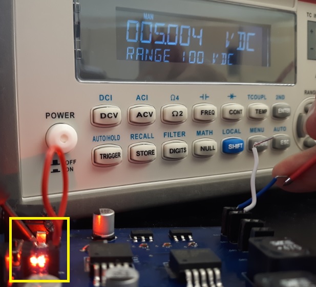
Figure 8. The
right 5V 3.3V 1A in pin is connected to power and the 5V output is
probed and shows 5.004V out.
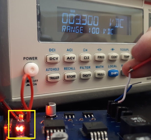
Figure 9. The
right 5V 3.3V 1A in pin is connected to power and the 3.3V ouput is
probed and shows 3.300 V.
5. Discussion
This introduction to Eagle PCB
was incredibly informative. The tutorials provided just enough
frustration to drill the experience into my head. The ERC and DRC
checks were very undescriptive so playing with the different
components, including the library devices, was particularly
educational. Redoing the components that I had done incorrectly the
first time was enlightening. The videos were very easy to follow. The
wiring of the physical components of the board was my
favorite part and especially enjoyable. This was my first time
soldering anything. It was rocky in the beginning; I completely missed
a pin for my LM2596 3.3V chip and I put a couple diodes in backwards.
After much debugging, the circuit board was functioning correctly with
the results shown in figures 6 - 9. I really enjoyed this entire lab.
The product of my hard work will be
well deserved and properly cherished.