ENGR338 Lab Spring 2021
Lab 1: Superposition, Thevenin's Equivalent Circuit, and LTSpice Review
Name: Audra Benally
Email: albenally1@fortlewis.edu
1. Title: Review Superposition, Thevenin's Equivalent Circuit, and LTSpice
2. Introduction: The purpose of this lab is to review the
superposition and thevenin equivalent methods to analyze circuits. The
analysis was completed via hand calculations and the calculated values
were verified with LTSpice simulations. LTSpice code was also reviewed
by using the separate .txt file technique. All the calculated values
were found and displayed in Figures 2, 4, and 5.
3. Materials and Methods:
Materials:
- Pencil and Paper
- Computer
- LTSpice Software
Methods:
Two separate circuits were
analyzed in this lab using the superposition and thevenin's equivalent
methods. Task 1 called for the superposition method. Hand calculation
are shown in Figure 1. The task 1 spice code and circuit values can be
seen in Figure 2. I decided to use the .op spice command for task 1 to
get an easy look at all the current and voltage values. Task 2 had us
use the thevenin's equivalent method to analyze the given circuit. Task
2 hand calculation can be seen in Figure 3. Task 2 spice code (for
original circuit) and simulation in shown in Figure 4. One cursor was
used to show the maximum voltage output in Figure 4. Two cursors were
manipulated to show the time delay from the simulation in Figure 5.
4. Results:
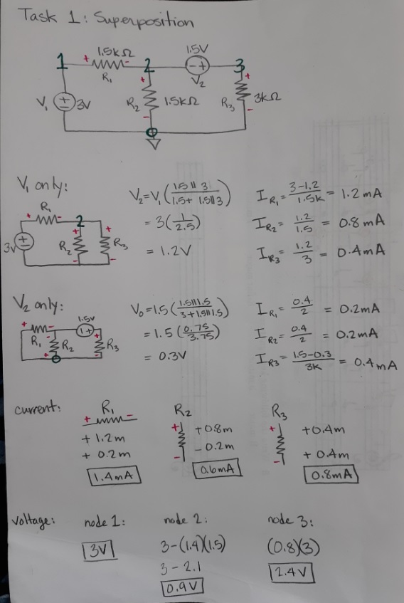
Figure 1.
Hand calculations using superposition to solve the circuit values.
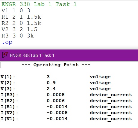
Figure 2.
LTSpice code and .op current and voltage simulation values.
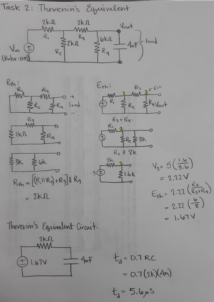
Figure 3. Hand calculations calculating the Thevenin's equivalent circuit to find the time delay (td).
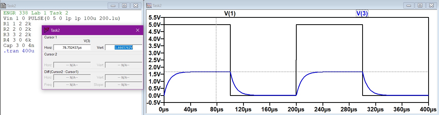
Figure 4, LTSpice code of
original circuit and simulation results. The highlighted value is the
Eth value in the hand calculations, and the value of the full Vout
charge.
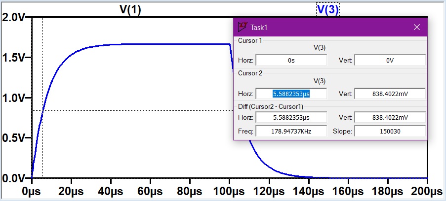
Figure 5.
Task 2 simulation with two cursors measuring the time delay
(highlighted).
5. Discussion
The purpose of this lab was to review important
methods that we will use to analyze upcoming circuits in this semester. This
lab was a great refresher on methods that I had only vaguely
remembered. The provided videos were a very helpful source for the hand
calculations. All the calculations were verified in the simulations and shown in figures 2, 4, and 5.
The only issue I had was tweaking the spice code for task
2. The values for the PULSE() function took a little while to find in
order to
show the time delay in action. The calculation of the time delay was
helpful with this problem. Overall, I would call this lab successful
and a good start for the lab portion of this class!