CE351 Lab 3 2020 Fall LEDs and SSDs
Name: Audra Benally
Email: albenally1@fortlewis.edu
1. Introduction
In this lab, LEDs are connected and programmed to blink.
The speed of the blinks are controlled with the code and with the
implementation of a push button. A seven segment display is also hooked
up and controlled both manually and with code. The seven segment
display is wired in various ways using first 7 wires, then 3 wires
using a decoder, then 1 wire using a shift-register.
2. The Code and the Results
LED portion:
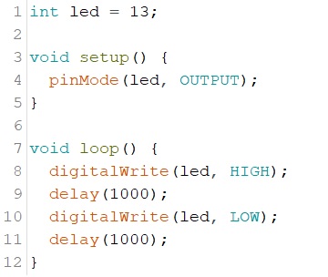
1.1 Blink the on-board LED:
Figure 1: Code to blink the on-board LED.
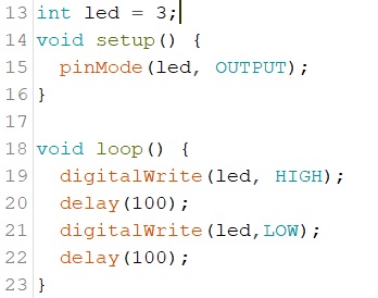
1.2 Blink an external LED:
Figure 2: Code to blink an external LED.
Video:
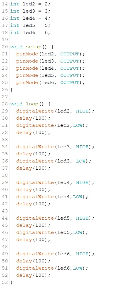
1.3 Running LEDs
Figure 3. Code for the running LEDs
Video:
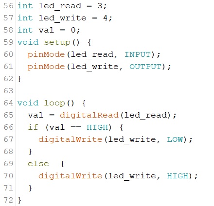
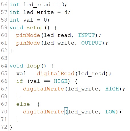
2.1 Push button to turn on, release to turn off
Figure
4. Code for push button to turn off led when button is pushed.
Video:
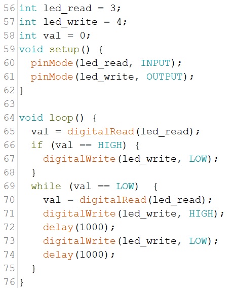
2.2 Push button to turn off, release to turn on
Figure 5. Code for push button, with HIGH and LOW changed so the opposite of 2.1 will occur.
Video:
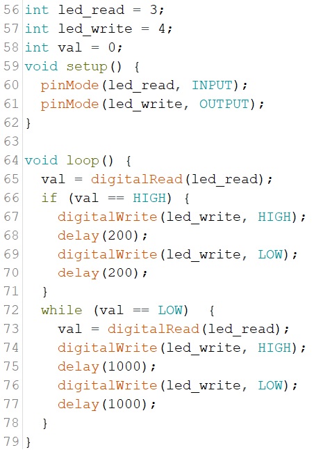
2.3 Push to blink the LED
Figure 6. Code for push to blink LED
Video:
2.4 Push to change blink speed Figure 7. Modified code to implement given function.
Video:
SSD portion:
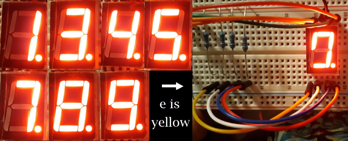
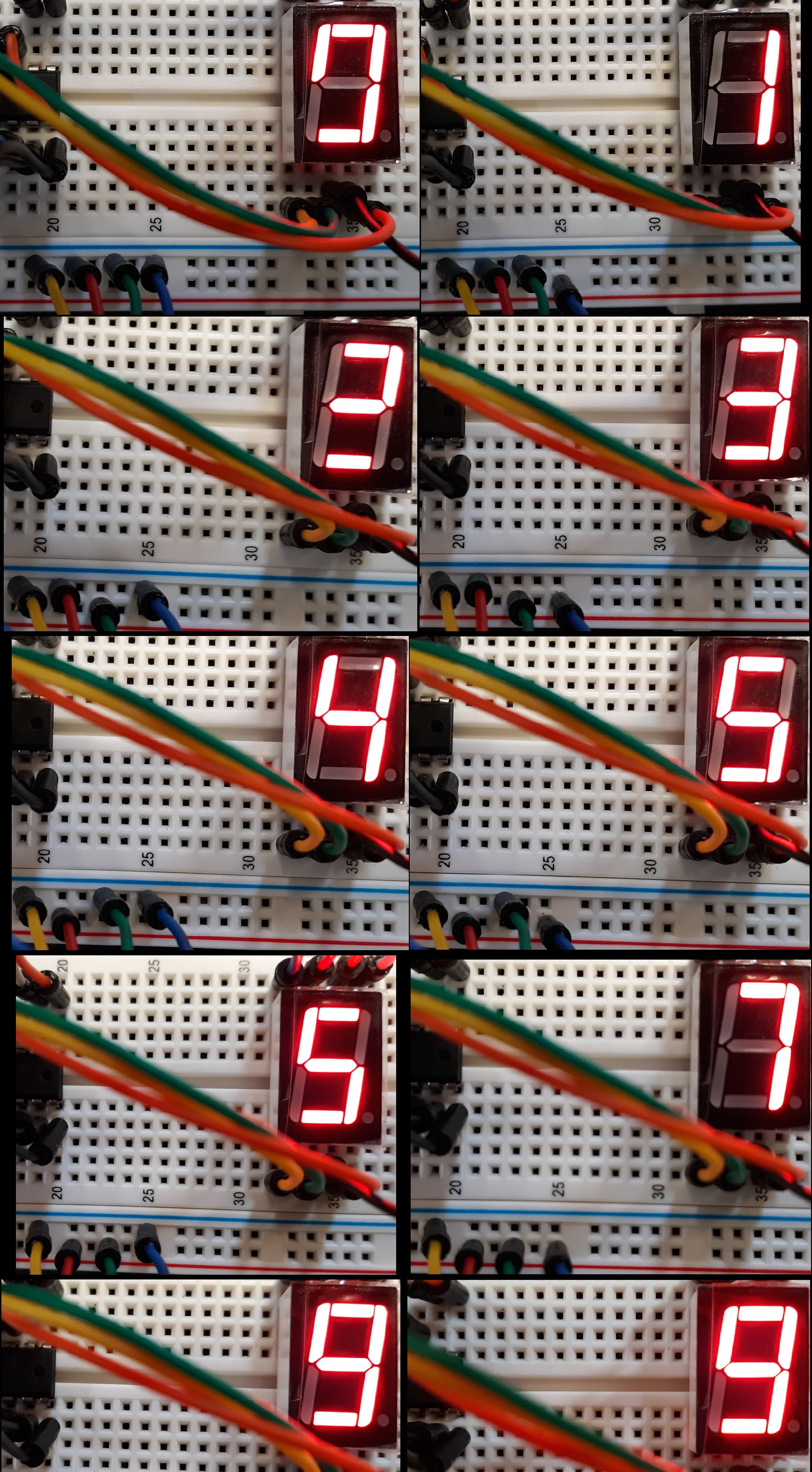
2.1 SSDs powered by 7 individual wires
Figure 8.
Different number displays using seven separate wires. I believe I fried
the e LED while playing with the different wires. I'm not sure how, but
the e is shown to be out on the right with the "0" display. Because of
this, I could only display certain numbers.
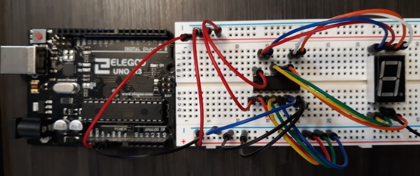
2.1 SSDs powered by 3 wires (manually)
Figure 9. Circuit using a decoder and three wires to control SSD.
Figure
10. All numbers displayed. Because the e LED is out, the A (blue), B
(green), C (red), and D (yellow) wires are shown with each number.
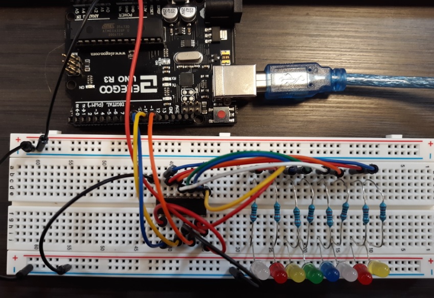
2.1 SSDs powered by single wire
Figure 11. Shift Register test circuit with 8 LEDs
Video:
To be continued... Discussion This was a very enjoyable. The leds are fun
to set up and the way the SSD works is fascinating. I appreciate the
way the SSD lab is set up: going from manually connecting each segment
LED to having a shift register chip to be able to control the entire
thing. It is interesting how logic and code slowly gets integrated into
making a more efficient seven segment display. I plan to continue with
this lab until it is completed because I really want to learn how to
set these SSDs up.