CE433 Embedded Systems Course Project Final Report
Name: Audra Benally Email: albenally1@fortlewis.edu
1. Title: Embedded Systems Pong Game Final Project
2. Introduction:
The two most widely used hardware language used for
FPGA programming are VHDL and Verilog. Of these two languages, Verilog
is more widely used in professional settings. In this CE433 class we
learned and practiced Verilog all throughout the course with the
mention of VHDL in our textbook. This project provided an opportunity
to take some time to understand VHDL and practice translating code from
VHDL to Verilog. This Pong Game was
initially created by Efe Acer (Youtube) / efeacer (github) who coded
the game in VHDL. This project was made of four main modules, a
constants file and a constraints file. The code files can be found at https://github.com/efeacer/PongGameVHDL.
Methods: For
this project, I had started with the "BallController.v" module. I
started reading through the code and got quite confused so I read
through some "VHDL and Verilog basics" online and in the
textbook. VHDL uses libraries that appear to be specific for its code
so I did not include it in the Verilog code. It seems that VHDL uses
more syntax words for its modules. The port declaration was easy to
understand but I had trouble with the "integer range" code. I
researched the equivalent to these words for a long while before I
decided to skip it and continue on. I would eventually get advice from
my partner, Ryan, on what to do for this declaration. We ended up using
"$clog2(constant)" as an equivalent range declaration for Verilog. The
signals were declared as registers with several initial assignments.
The "if move'event and move='1'" was translated to an "always @(posedge move)" block. If
statements in VHDL were easy to understand and only needed slight
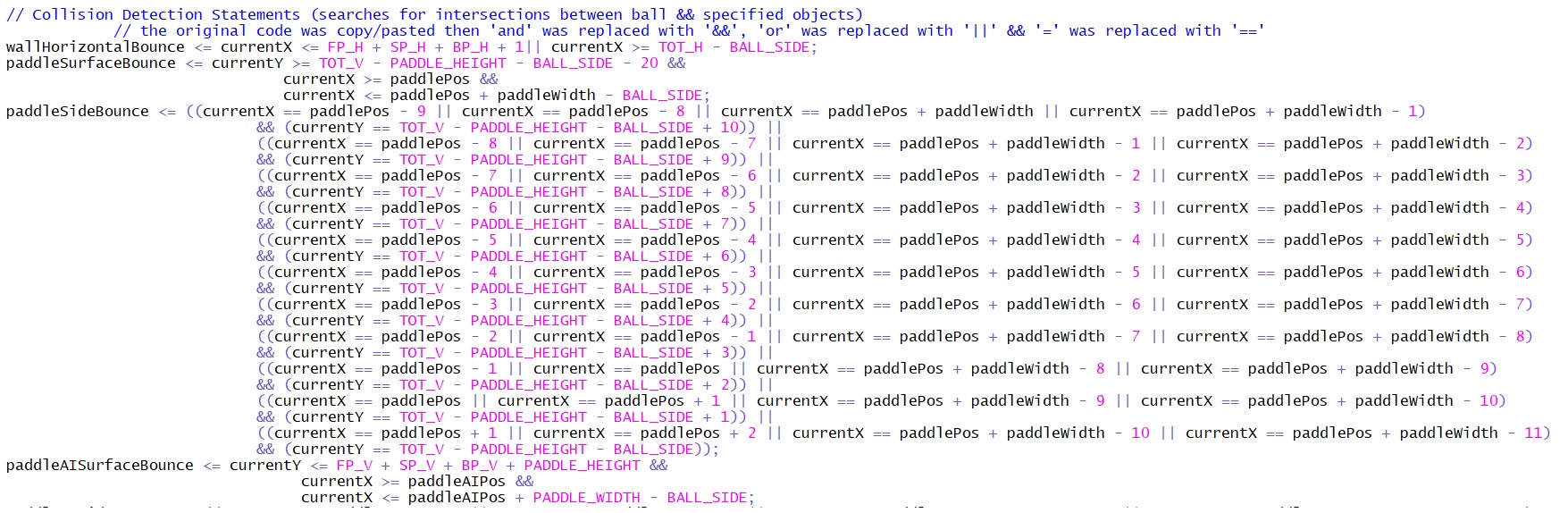
changing to translate into Verilog. For the collision detection, the
code seemed very similar to Verilog with different "&&" and
"||" and "==" symbols. Because of this, and because I didn't want to
mess up the collision logic, I had copied the original code and pasted
it into my Verilog module. Then I replaced all the "and"s, "or"s, and
"="s. I did the same with the rest of the logic. For the register
updates for position, play, new game, ai won, and player won, I
assigned these registers outside the "always" block. Then, I ended the
module. Next
I had translated the VGAcontroller.v module. By the time I had finished
this, Ryan was done with the rest of the modules and sent them over. I
put all the modules and constants and constraints file in Vivado and
synthesized the code. I went through a couple trial and error
synchronizations and tweaked my code to make it through. Oftentimes it
was issues with register assignments and data sizes. There were also
issues with the bitmap assignment technique. We found that Vivado did
not assign bitmaps in the same way and so I opted to assign the data
one line at a time. Ryan had done a lot more than I had when it came to
debugging and I kept updating my code with his. When I got to a point
where the screen wasn't showing even though the bitstream was
successful I had decided to take a break and work on the logo. For
the logo, a bitmap is used with ones and zeros for the on or off pixel
data. I decided to use excel because I understood the program from past
experience. I copy pasted the "logo" data assignment into excel and
separated the assignment code and the bit data. I used the "=" sign to
separate using the text to column tool under the data tab. I made a
square of equivalent size which was 200x165. I used zeros and color
fill to design the logo and then replaced all the empty space with ones
using find and replace. I then used the code
'=A1&"="&CONCAT(B1:GU1)' for the first line. The A1 cell had
the words "assign logo[#]" and the bits from 0 to 199 as well as ";"
were in cells B1 through GU1. This combined all the cells that had the
logo design in the first row. This also re-inserted the '=' assignment
code since I got rid of it to separate the code initially. Then I
dragged the code down using the little square in the bottom right of
the selected equation cell. This applied the equation to the rest
of the lines and combined everthing else. From here I just had to
copy/paste the bitmap code into verilog. The only issue I had was that
I had rectangular cells that skewed the dimensions a little and made
the actual logo in the game look wider than anticipated. For
the rest of the project I struggled through several issues and I believe
Ryan had much more understanding than I did. He was able to get the
code to work better in the time we had left before the presentation.
After realizing this, I decided to spend my time preparing the
presentation slides. Ryan
had described all the bugs he was working through and hopefully, I was able to portray these issues
on the slides. 4. Results:
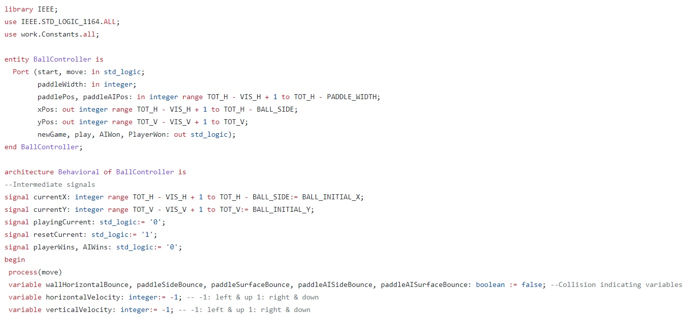
Figure 1. Start of BallController VHDL module.
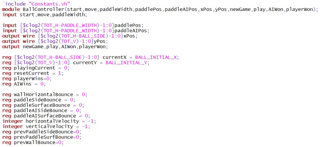
Figure 2. My
Verilog translation of the same amount of code that is seen in figure 1.
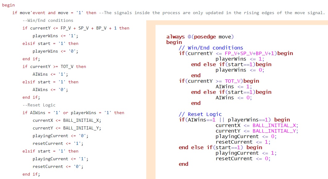
Figure 3. If
statements for both of the languages. VHDL on the left and Verilog on
the right.
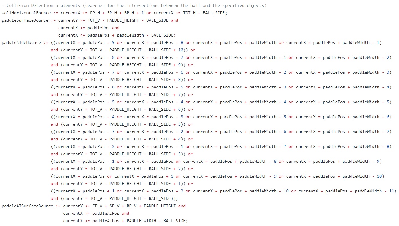
Figure 4. VHDL sample of the collision detection.
Figure 5.
Verilog code of the VHDL sample of collision detection seen in figure 4.
Figure 6.
Bitmap code design in excel with a little bit of the concatinated code
on the right side.
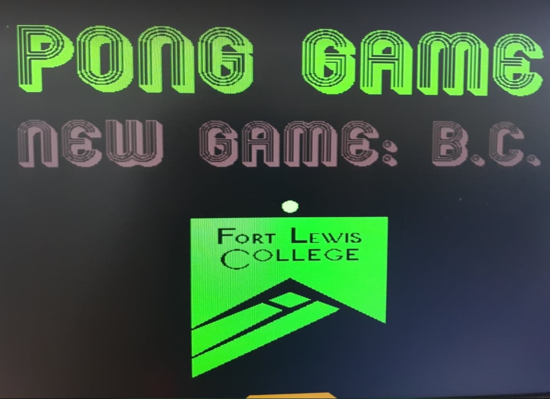
Figure 7. Fort Lewis College logo in the actual Pong Game.
Figure 8. Full picture of the start menu.
Video 1. Demonstration of the Pong Game. Video link: https://youtu.be/MVxFXld9DbY
5. Discussion:
In this project we tried to
recreate a Pong game that was originally coded in VHDL. For this
report, I wrote about all the portions of the lab that I had helped
with. Ryan was much more knowledgeable about the translating process
than I. By the time I got the hang of the translating, Ryan had
finished a lot more than me. Issues that were encountered and not fully
resolved were the collision logic with the AI and player's paddle. Ryan
believes it is the ball movement clocking and that changin the
"BALL_PRESCALER" will resolve the issue. He had partially resolved the
issue with the AI paddle by using this method.
To understand these issues, refer to the demonstration video. First in the video, you will see the
difficulty selection happen using the switches. The difficulty is
controlled by changing the size of the player's paddle. Then you will
see the game start several times with the issue of the AI not being able to hit the ball. On the fourth
try the AI is able to hit the ball with the side of the padde. You will
then see that the player's padde is not able to hit the incoming pong
ball. This is shown by the ball flying right through the player's paddle.
This process was very
informative and I was happy to get the opportunity to practice an event
that could occur in my future career. Even though I caught on slower
than Ryan I enjoyed making my way through the translating process. I
was informed that MatLab may have been an easier option for creating
the bitmap and this made me realize that I may need to change my habits
for the future if I was to be more efficient. Overall, I enjoyed this
project and the experience that came with the translating procedure.