Lab
3 Pushbuttons, LEDs, and DC Motors
Outcome
of this lab:
1. Be able to use pushbuttons as switches to control a circuit.
2. Be able to use LEDs in a circuit.
3. Be able to turn on and turn off a DC motor using the bench-top DC power supply and using a motor driver.
4. Be able to use a photoresistor to control the speed of motors.
Instructions:
1. Pushbuttons and LEDs
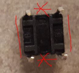
The pushbutton: If you flip the pushbutton, you will see there are two
lines indicate the connection of the four pins before the button is
pushed.
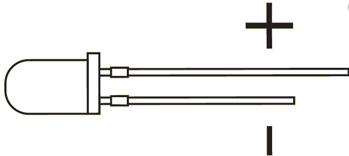
The LED lights have
two pins. The longer one is the anode, the shorter one is the cathode.
To turn on the LED, the anode should have a higher voltage potential
than the shorter pin.
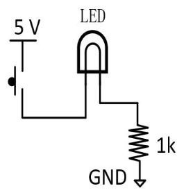
The LED needs a resistor to protect it from being burned by the
current. The LED itself has low resistance, if there is no resistor in
the circuit, it will draw a significant amount of current from the
power source which will burn the LED or reduce its life-span. The
resistance of the resistor can be anything between 500 ohm and 1k ohm.
Task 1.1:
Make the following connecctions on a breadboard to turn on and turn off
an LED. Take pictures of your demonstration for the report.
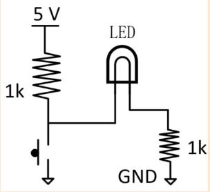
Task 1.2:
Use the following circuit to demonstrate that if you push the
pushbutton then the LED will be turned off. Take pictures of the
results and explain why this occurs in the report.
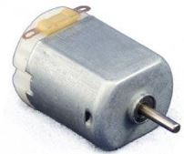
2. DC Motors
The motors are the 'engine' of the robot car we are going to work on in
the project of this course. A DC motor is controlled by DC voltages,
which means having DC voltages applied to the two terminals of a DC
motor:
A DC motor draws a lot of current (50 - 100 mA). Regular logic voltages
such as 3.3 V or 5 V are not sufficient to drive a DC motor
efficiently. We need an individual power supply to provide enough
driving capability. A motor driver integrated circuit is usually used
to receive logic commands and convert it into real driving current for
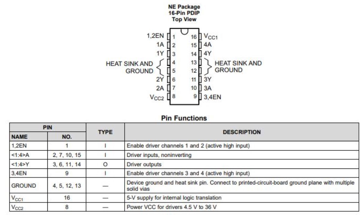
motors. We will use L293D for this project. Read the pin map and the table very carefully:
The first thing you want to test is if the L293D you have can drive a
motor. So you don't need to build everything on robot car yet, instead,
just build things on a breadboard, control the wires/inputs manually,
see if the motors run. By the way, try higher voltages see if the motor
will run faster.
The first test is just verify that you understand how the motor is driven by L293D, and how to make the motor runs.
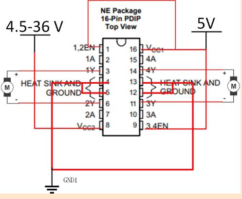
The real circuit on a breadboard:
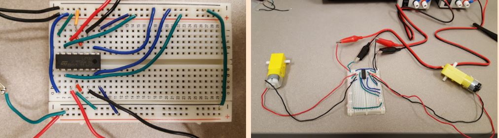
Task 2.1:
Build the circuit on a breadboard, use L293D to drive two DC motors.
Task 2.2:
Add two pushbuttons to the circuit so you can push the pushbuttons to turn on/off the motors.
Task 2.3:
Try three different voltages for the pin VCC2 on L293D: 6 V, 9 V, and 12 V.
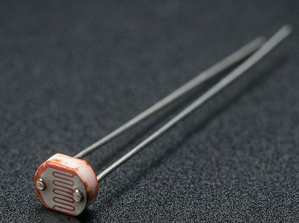
3. Photoresistor
CdS cells are little
light sensors. As the squiggly face is exposed to more light, the
resistance goes down. When its light, the resistance is about 5-10KΩ,
when dark it goes up to 200KΩ.
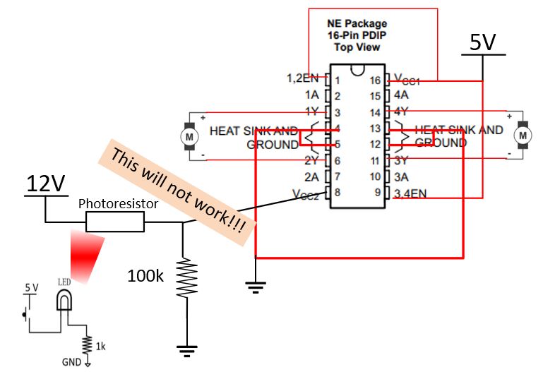
Task 3.1:
The initial purpose of the forllowing circuit is to control the speed
of the motor INDIRECTLY using the photoresistor. However, due to the
low input resistance of the VCC2 pin, the parallel resistor was
'killed' by the chip. So the following circuit won't work.
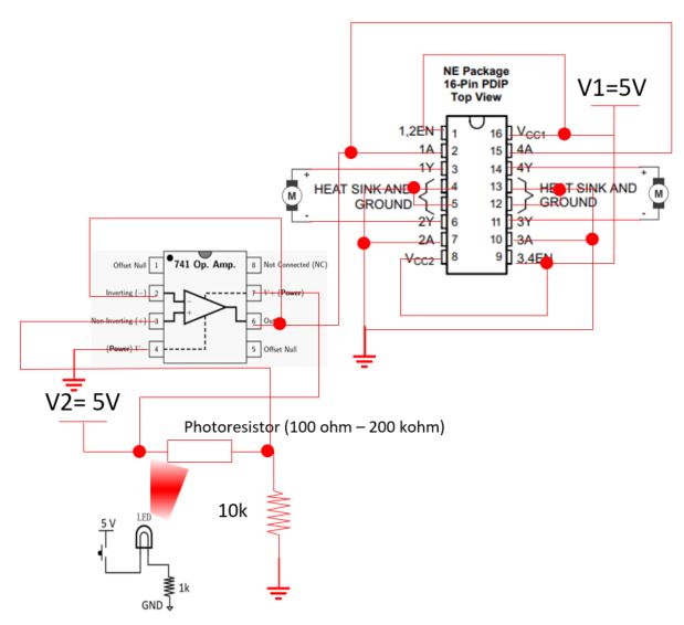
However, we can still use the photoresistor to turn on/off the motor using the schematic below.
The following one works. Use a box to cover the circuit. When the button is pushed, the motor will be turned on.
The '741' chip is an
operational amplifier which can isolate the input from the output. Now,
the output voltage of the voltage divider is being connected to the
input of the amplifier (gain = 1), the output is connected to '1A' and
'4A' to turn on/off the motors. So the output of the voltage divider is
isolated from the low input resistance of the driver.
(never mind if you
don't understant it, we will learn amplifiers later this semester. For
this lab, you just need to make it work).
-- The end of the lab